Facebook
 Google
 GitHub
 Linkedin
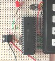
JJW,How is the oscillator configured?
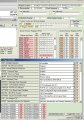
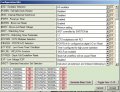
Show us the osccon register.
It should be HS-crystal and PLL not enabled.
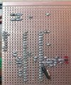
You might need a series resistor between crystal and osc2-pin, see the docs.
I assume that if the config settings are HS, then PLL is not enabled?
I added 330 ohm Rs, between OSC2 pin and XTL, but no 'singing'
I have 20 MHz low profile XTL and 22pF ceramic disk caps at the moment.
Camerart.
Attachments
-
 281.5 KB Views: 18


")