GIC Oscillator build

Thread Starter

Joofmom

Joined Jan 17, 2025
5
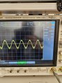
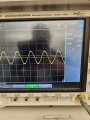
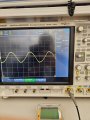
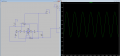
Hello, I'm building a GIC resonator for the beginning stage of a sine-square-triangle converter, which should have a bandwidth of 50kHz. The circuit (attached picture) works amazing in sim of course. The values I've used allow a decent looking sin wave from 1kHz to around 50kHz at the output. However, building this (just the GIC only) on a breadboard I get a beautiful sine wave but with a frequency in the megahertz (around 1.6). Frequency is controlled in the same range (50kHz) as simulation through the potentiometer (R18 in picture), but I have this baseline massive frequency it sits on. I am using an LM833 for the build, which has a similar slew rate to the one in simulation. I have access to LM318, LM833, LM358. Assuming the build has been done according to the simulation, can anyone help me understand as to why this frequency is ending up so large vs what is on simulation? I'm a student so i'm learning, would greatly appreciate some insight. I've attached an article which explains the GIC as a reference, as well as a picture of my GIC circuit.

Thank you kindly

https://www.researchgate.net/public...ructure_and_its_application_to_RC-oscillators
 

Attachments

Thread Starter

Joofmom

Joined Jan 17, 2025
5
Have a look at figure 2 of the attached document.
Thank you for the response. I have seen this article and did use this equation to adjust for the necessary frequency on simulation. It's just the actual build does not give me the same result, frequency wise. I suspect it's do to do with the fact theyre using 741? I did however try a 358 which has a similar slew rate and it didn't work at all. Pulling my hair out about this
 

Bordodynov

Joined May 20, 2015
3,430
I have an LM324 transistor model. To remove the distortion, I added resistors to the output. I also added a chain of diodes and a resistor to get the desired output amplitude.

1740032743258.png

1740033875268.png
 
Last edited:

LvW

Joined Jun 13, 2013
2,019
However, building this (just the GIC only) on a breadboard I get a beautiful sine wave but with a frequency in the megahertz (around 1.6).
Sorry for the silly question - are you sure that on the breadbord you have used the same parts values as in simulation?
 

LvW

Joined Jun 13, 2013
2,019
Each resistor and cap values were tested prior yes. It's ok, those silly mistakes do happen!
As the author of the GIC-resonator papers I can inform you about a modification which - perhaps (hopefully ?) - helps a bit to solve your problem:
In your circuit, you can make R19=0 (short circuit) and also R20=0.
Instead, you can connect a LARGE resistor Rp between the common node of both inverting opamp inputs and ground.
This modification is explained in the paper as referenced in post#2.

In the present (classical) configuration, the input impedance can be seen as a series combination of a frequency dependent part and a (small) negative resistance (necessary for start of the oscillation).

In the alternative configuration, the input impedance can be seen as a parallel combination of a frequency dependent part and a (large) negative resistance - equivalent to the sum of two admittances.
 
Last edited:

Thread Starter

Joofmom

Joined Jan 17, 2025
5
Welcome to AAC.

Is this an assignment for academic credit?
As the author of the GIC-resonator papers I can inform you about a modification which - perhaps (hopefully ?) - helps a bit to solve your problem:
In your circuit, you can make R19=0 (short circuit) and also R20=0.
Instead, you can connect a LARGE resistor Rp between the common node of both inverting opamp inputs and ground.
This modification is explained in the paper as referenced in post#2.

In the present (classical) configuration, the input impedance can be seen as a series combination of a frequency dependent part and a (small) negative resistance (necessary for start of the oscillation).

In the alternative configuration, the input impedance can be seen as a parallel combination of a frequency dependent part and a (large) negative resistance - equivalent to the sum of two admittances.
What a pleasure to speak with you sir. Thank you for the advice, I missed that part when I read the article. I do want to say, for the record and anyone who may find it useful, that I've figured out the issue and have now been able to generate a sin wave using the GIC from 5-55kHz. I used the LM833, the issue was that I was using two seperate supplies for the rail voltage. It looks like the slight delay in time from pressing both power buttons created very high oscillations. Using a single dual power supply fixed the issue. Cheers and thank you for the responses all.
 

Attachments

LvW

Joined Jun 13, 2013
2,019
I've figured out the issue and have now been able to generate a sin wave using the GIC from 5-55kHz. I used the LM833, the issue was that I was using two seperate supplies for the rail voltage.
Thank you for this positive message - and good luck for your further work.
 
Top