Genie Garage Door problem

bwilliams60

Joined Nov 18, 2012
1,442
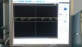
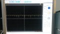
Here is what you should expect for voltage according to my GENIE garage door opener.
Across two wires:
Unplugged - 5.0 VDC
Plugged in - 3.37 VDC unlocked/1.36 VDC locked
Light - 2.39 VDC
Garage Up/down - 0.00 VDC

Hope that helps. Looking for different voltage levels to controller inside main unit. Yours may be a little different but suspect they are very similar in operation.
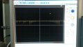
 

Thread Starter

Tonyr1084

Joined Sep 24, 2015
7,899
Hope that helps.
Thanks B. Nice to see you again.

Went shopping and couldn't find a replacement switch. Will probably have to mail-order one.

Last night when testing the switch I used my scope on AC Coupling. The voltages were so small I didn't want to chase them all over the screen just to have a look at the waveform. Thanks for the numbers, I'll give that a go.

Funny, my Genie 2000 - I can short the leads and the door will actuate. Not so with the 1000.

I've swapped out the 1000 that was in service at the time of failure with the 1000 I used for six months before motion sensor failure. I'm using the board out of that unit and the one that WAS in place I now have down stairs on my test bench. Nothing I do gets it working. There's power on the board, the pig-tail fuse is good. The bridge rectifier is good. The main cap appears to be good. Beyond that I can't seem to find any response. I've been busy and haven't had time to dig into it but in the coming days I will. For now the other unit is working fine using the remotes. I can program in remotes and do whatever else it's supposed to do - except operate the door from the wall switch.

Armed with your numbers I'll give that a test and see what comes of it. But from prior testing, I couldn't get the lights to respond.
 

Thread Starter

Tonyr1084

Joined Sep 24, 2015
7,899
Well, I broke out the Hantek computer based scope. Here's the traces I've seen.

Door Button trace is erratic. Timing is good but voltages are swinging up and down, sometimes 120mV sometimes 850mV. Sometimes they appear sinusoidal (sort of). Light and Lock button traces are similar in nature. I think it's a foregone conclusion, the wall switch is toast. It's possible the head unit failed and shocked the wall switch. The head unit is currently non-functional. Fortunately I have a second head unit in its place. But with the functioning head unit the wall switch still fails to command the head unit.

Bwilliams: I think you're reading a Series II (series 2) switch.
 

Attachments

Last edited:

Thread Starter

Tonyr1084

Joined Sep 24, 2015
7,899
The thing about the waveforms is that there is no repeating pattern. Timing remains constant but it would appear a transistor or maybe a capacitor is not holding its value. As for giving up on it - I think I'd like to mess with it and see what I can learn in the process.

At present I'm waiting to hear back from Genie regarding what i've found. But here's what I CAN tell you - the head unit failed. It doesn't power up. I've traced power into the power supply but haven't gone any further to check for any output - that's not on my list of things to do. Meanwhile, a second head unit is up and operational. So I'm not having issues with opening my garage door. But as yet I have not solved the problem of the "Button on the wall".

Bwilliams60 mentioned voltages he's reading on his GDO. From what he said it appears he's looking at a series 2 system, where you CAN short the leads to trigger the door. I don't recall for certain being able to trigger my series 3 door opener by shorting the leads, but at present no matter which head unit I have, the door would not be activated by a dead short. That's why I'm waiting to hear from Genie regarding whether dead shorting a series 3 will work or not. If it WILL (or is supposed to) work then all I really need is a door bell button. I've never used the lights or the lock for anything before. But judging from the inconsistent waveforms I've posted, which have no repeating pattern, it would appear that shorting the leads will result in no actuation. Though it's worth mentioning that when I installed the series 2 wall switch, pushing the door button or the light button ONLY turned the light on or off. When I pushed the LOCK button then the other two buttons would not do anything. But on the series 2 switch, the Lock button was a mechanical latching switch. So it may be as simple as disconnecting from the main control wires. But I don't know for sure. And I haven't bothered to investigate that part of it.

Nevertheless, series 2 will not work on a series 3 system. I haven't tried the supposedly dead series 3 on the series 2 system. From what I've seen in testing I don't think it will do anything on that unit either.

Albert: Feel free to drop me a line. We can discuss sending this thing to you. Not sure I will but - eh.
 

Thread Starter

Tonyr1084

Joined Sep 24, 2015
7,899
The last POOP!

Spoke to Genie. They believe I have a two fold problem. They believe I have bad wire - but I debunked that. Using 6 inches of 18 gauge wire connected each to my two wall switches, series 2 and series 3, the main garage door just does not function from there. According to the serial number I should be operating off of a series 2 console, but using a series 2 console does not operate the door. So they're sending me a new head unit board AND a series 2 console. The two will be a matched set. Hence forth I will forever only need series 2 console. Which is nice because I can add as many door bell buttons as I like and operate the door from many different locations.

Cost to me is shipping only of $8.42. Will arrive within four days. Gotta love GenieCompany. I'm STILL going to mess around with the other stuff. Since the light works I can use the old mother as a remote light switch.

Anyway, that pretty much wraps it up.

Oh, I've been checking the bad series 3 switch. The 555 is oscillating normally. Some of the diodes are likewise passing the signal through cleanly. Only after a few transistors am I seeing noise get into the signal, which may account for the degraded wave forms. Otherwise, every waveform should be uniform (not appear to be sinusoidally active). Good lesson on noise control.

Peace y'all. And thanks.
 

jkwilborn

Joined Jan 26, 2016
32
Did Genie give you any clues on how this works exactly? It's a cheap fix, so I wouldn't complain, if it fixes it.

Just wondering around these lines...

I've been reading these and I can't put together how it operates, if the operation is modulating the 5v power line...? Even a few millivolts modulation would assume a power supply that was either designed to be under powered (or tolerate this variation) or some kind of resistance between it and the power supply itself. Otherwise the supply would swamp whatever is pulling it down (modulating it.)

Could it be a problem that these measurements are done with a system that is already in failure? So it isn't working and the measurements you've taken may not be what is supposed (or even in the ball park) normal operation would be?

It seems that the search for an explanation has not been fruitful one on the Internet or from Genie?

There must be some other approach to how this is working.

Maybe it's some kind of PWM communication link? Like when they are not talking there is enough current/voltage available for the switch board to be parasitic in nature on the supply line (which really could be the communication line, pulled to Vcc when not 'communicating'). The line being pulled down (as in 'wired or') would support this approach. This technique is becoming more common as IC's (like cmos timers?) are only requiring current in the nano amp range. I'll hunt around for an explanation, if there is interest. I know I used this, just can't remember where...

Thanks
 
Last edited:

Thread Starter

Tonyr1084

Joined Sep 24, 2015
7,899
There are three different time codes: The shortest code (working from memory I don't recall the exact frequency) operates the garage door. It drops the voltage by about 380 mV. You start with a 5 volt signal that is steady. When you push the button it rings the 5 volt line with pulses. The opener reads that as a command to open (or close) the door. The next frequency lower (by half) operates the light. The NEXT lower frequency operates the command to lock the system.

If you've looked at the traces I've uploaded you can see that the 380 mV is not consistent. Sometimes it acts (in amplitude) like a sign wave, other times like a saw tooth wave, and still yet other times it just appears to be random amplitudes that never go exceed the 380 mV drop.

When I scope the output of the 555 I get a good and clean square wave (depending on which button is pressed the frequency changes). The first diode (marked D4 I think) somehow seems to be inverting the signal. It is marked with the same markings as the other diodes, so I don't understand exactly what's going on, but somehow, the signal that is normally low with a high pulse turns into a high with low logic level pulses. From that point is the last place where the wave form is clean. After that it gets really ugly.

Since Genie is sending me a new board and wall console I've not given it any more attention - there is a current family issue going on that has demanded most of my attention. Not to worry, family issues will be worked out soon. Meanwhile, I'll get back to it if for no other reason - curiosity how they do it.
 
Top