Facebook
 Google
 GitHub
 Linkedin
The door works from the remote but does not work from the wall switch. The safety beams are working properly. The wall switch has a red LED that is lit. The wiring is all good, but when you push the button to open or close the door nothing happens. Nothing at all.
The wall switch has three functions: 1) to open and close the door. 2) to activate the garage door opener light. 3) to lock the garage door opener (prevent it from running).
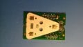
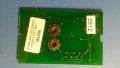
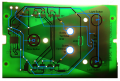
Upon opening the switch there's quite a bit more circuitry in there than I thought would be. The board is about 1" by 2". I even tried shorting the wires from the switch but nothing happens.
I get the feeling it's going to be needing a new wall switch but I hate to spend money without fully diagnosing the problem(s). Any advice? And if anyone says "Google it!" FORGET IT! Already tried. Found a site that would answer all my questions if I promise to pay a fee. Couldn't find ANY free troubleshooting guide.
The wall switch has three functions: 1) to open and close the door. 2) to activate the garage door opener light. 3) to lock the garage door opener (prevent it from running).
Upon opening the switch there's quite a bit more circuitry in there than I thought would be. The board is about 1" by 2". I even tried shorting the wires from the switch but nothing happens.
I get the feeling it's going to be needing a new wall switch but I hate to spend money without fully diagnosing the problem(s). Any advice? And if anyone says "Google it!" FORGET IT! Already tried. Found a site that would answer all my questions if I promise to pay a fee. Couldn't find ANY free troubleshooting guide.