Generate 1 to 255 Hz, variable and controlled by arduino

Thread Starter

davidbr

Joined Apr 25, 2018
60
Hi all,
As always get a lot of help here, I dare to hope that this time will be the same :)
So the issue is that I need to generate 1 to 255 Hz frequency and this have to be controlled by an arduino. I am playing with a 555 now and my first idea is to use it combined with a digital potentiometer to actually set the frequency. I found a lot of calculators on the internet but was not able to decide some values for the potentiometer in order to get steps for about 1Hz.
Do you have any idea how can I achieve this? Or maybe using 555 is not a good approach ?
Thank you very much
 

MrChips

Joined Oct 2, 2009
34,954
How do you intend to control it with the Arduino?
What do you want to control from the Arduino?
  • frequency
  • duty cycle
  • pulse amplitude
  • trigger input
  • duration
1-255Hz is not considered fast. You don't need a 555-timer circuit for this. You can generate the signal entirely from the Arduino.
Do you want to generate square waves, 50% duty cycle, or some other kind of arbitrary waveform such as sine, triangle, saw-tooth?
 

Picbuster

Joined Dec 2, 2013
1,059
Hi all,
As always get a lot of help here, I dare to hope that this time will be the same :)
So the issue is that I need to generate 1 to 255 Hz frequency and this have to be controlled by an arduino. I am playing with a 555 now and my first idea is to use it combined with a digital potentiometer to actually set the frequency. I found a lot of calculators on the internet but was not able to decide some values for the potentiometer in order to get steps for about 1Hz.
Do you have any idea how can I achieve this? Or maybe using 555 is not a good approach ?
Thank you very much
Simple solution:
use an arduino timer interrupt
use the output from the potmeter converted to digital value to reset the timer register.

that's all.
good luck

Picbuster
 

Thread Starter

davidbr

Joined Apr 25, 2018
60
Ok, I will rephrase because I think is not clear what I want to achieve :
I have a device that measure RPM and need a frequency input. What I want is to simulate an input for this device.(By default as input there is some sort of tahometer).
From my tests with arduino pwm :
If I generate 10Hz then device read - 1198RPM (somehow double the value, because normally on 10Hz I should have 600 RPM)
If I generate 11Hz then device read - 1318 RPM
and so on...
Basically step that I increase RPM on device is around 120RPM. I need to have step of about 10RPM or at least 50 RPM but I am not able to with arduino 10.5 HZ ro better 10.x Hz (where x to be from 0 to 9 ).

Ideea with 555 was to control it with arduino using a digital potentiometer.

So I am open on any suggestions / hints

Thanks
 

ericgibbs

Joined Jan 29, 2010
21,487
hi David,
Can you check, if your RPM reading tacho device is designed to read pulses edges.?, some do.
That would account for the doubled RPM reading.
Do you have a tacho spec sheet or link to post.?
E
 

Thread Starter

davidbr

Joined Apr 25, 2018
60
Hi,
I am not able to get that info unfortunately but I did tests with many values and I am sure that the reading is doubled.
Is there any way to test somehow and answer to your question?
 

ericgibbs

Joined Jan 29, 2010
21,487
hi,
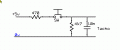
You could use a push switch as an input to the tacho.
And check if the tacho increments when the switch is closed and opened.
Do you know how to set that up.?
E
 

Thread Starter

davidbr

Joined Apr 25, 2018
60
Thanks a lot for the idea but I am not sure I am able to understand that. You mean a like a push button which open 5v?
 

Thread Starter

davidbr

Joined Apr 25, 2018
60
I have them all. Will do the test now.
Thanks
L.E. - I just tried but nothing happen. So does not read anything even if I press super fast on switch or not...
 
Last edited:

Thread Starter

davidbr

Joined Apr 25, 2018
60
But this is for due (which is not a problem cause I have a due also) but as far I can see from code the step is also around 1.hz, right/?
 

LesJones

Joined Jan 8, 2017
4,509
I was only suggesing it as a basis for writing your own code. I think it should be possible to change the resolution to 1 Hz. I am very poor at writing in "C" so I would use assembler.

Les.
 

ericgibbs

Joined Jan 29, 2010
21,487
Thats very strange.
As you say that you want to use the tacho 1Hz thru 255Hz, is it possible that your tacho has a minimum RPM restriction.?
 

ericgibbs

Joined Jan 29, 2010
21,487
hi David,
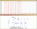
If that switch test circuit has been built and connected correctly to the tacho, I do not a reason why it is not working.
Its a simple circuit that is often used to send a pulse into a circuit.
E
 

Attachments

Top