Gated astable problem

Thread Starter

szabikka

Joined Sep 3, 2014
113
Hello everyone!

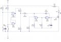
During experimenting I ran into the following problems. I built a gated astable from nand gates which is turned on and off by a nand bistable. The circuit can be seen in the attachment called 'circuit1'. As you can see the bistable is interfaced to the astable via an n-channel mosfet. The two diodes make sure that pulse completion occurs when the bistable is flipped during a high astable pulse and therefore the pulse is not shortened. This circuit works as it is supposed, I have tested it on a breadboard. However, I am not sure if the pull-down resistors marked R5, R6 and R11 are needed, if someone could help with this small question, I would greatly appreciate it.

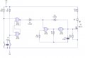
My other problem is that I tried to omit the mosfet to see if the circuit is still functional in this new configuration, but this time oscillation did not occur. The circuit can be seen in attachment 'circuit2'. When the bistable is set, the LED is continuously lit and it's not blinking as it should. My question here is what causes this behaviour and is there a way to leave out the mosfet and drive the astable without interfacing?

Thanks for the replies in advance!
 

Attachments

Alec_t

Joined Sep 17, 2013
14,313
You need a pull-down resistor from the diode cathodes to Vss, otherwise the gate input is floating when the diodes are cut off.
R11 is unnecessary, as the CMOS gate driving the FET has a push-pull output.
 

RichardO

Joined May 4, 2013
2,270
First, answers to your questions for circuit1. R6 and R11 are not needed. The outut of the gates will go to zero volts or the power supply without them. R5 is needed to supply a path for the leakage current of the FET. Otherwise, the leakage current will go through the diode to the input of gate "c".

There is a problem with circuit1 that you did not catch. When both diodes are off (reverse biased) the gate input is floating. With CMOS, the floating condition is never allowed. It can cause unpredictable problems and will cause the CMOS chip to draw excess power. The solution is to ad a high-value resistor from the junction of the 2 diodes to ground. In your circuit, I think any value from 100k to 1Meg ohms should work.

Try adding the same missing resistor to circuit2 and see if it starts to work. I may not work exactly the same as circuit1. The start/end voltage of the oscillator is a function of the voltage on the left side of D3. In circuit1 this was set by the Vgs of the FET. In circuit 2 you may want to try using a voltage divider to bias the junction of the diodes to a voltage other than ground.


edit: fixed typo
 

Thread Starter

szabikka

Joined Sep 3, 2014
113
Thank you for the replies! Especially, that both of you pointed out the missing pull-down on the diodes' cathode.
 

Thread Starter

szabikka

Joined Sep 3, 2014
113
Hi again!

Just thought I'd share the results. The missing pull-down on its own didn't solve the problem, but by adding a voltage divider in the configuration in the attachment worked. Thanks for the tip Richard!
 

Attachments

ScottWang

Joined Aug 23, 2012
7,398
Have you ever consider to take the R10, R14, R15, D4, D5, C3 away, and connect directly from the output of IC2a to the input of IC2c?
 

RichardO

Joined May 4, 2013
2,270
Hi again!

Just thought I'd share the results. The missing pull-down on its own didn't solve the problem, but by adding a voltage divider in the configuration in the attachment worked. Thanks for the tip Richard!
Glad it works. But... an admission. I had in mind something different than what you did. But, I can't argue woth sucess. Now I have to understand what you built. :D

Keep in mind that doing voltage dividers on logic inputs can create problems. The thresholds are very unpredictable and sensitive to temperature and power supply voltage. even worse, is that the divider may put the gate into its linear region. This can cause a large power supply -- maybe enough to damage the part. I recommend that you measure the power supply current of the oscillator chip to be sure that it is ok. Do this measurent with the LED both on and off.
 

Thread Starter

szabikka

Joined Sep 3, 2014
113
Richard, I was worried about the same thing when I built it, but I measured the current output of the gate and its only about a hundred microamps. According to the datasheet at 12V power supply the gates can source about 1,1 milliamps, so it's fine. By the way, can I ask you to draw the voltage divider as you had it in mind?
 

Thread Starter

szabikka

Joined Sep 3, 2014
113
Have you ever consider to take the R10, R14, R15, D4, D5, C3 away, and connect directly from the output of IC2a to the input of IC2c?
Scott, I think the diodes are needed for the pulse completion, so when the bistable is flipped in the reset state it doesn't shorten the last pulse.
 

ScottWang

Joined Aug 23, 2012
7,398
Scott, I think the diodes are needed for the pulse completion, so when the bistable is flipped in the reset state it doesn't shorten the last pulse.
If you have special concerned then you can keep it, and the other take away do they have affecting anything?
If not, save the parts and the circuit become more less parts will be better.
How is the C3, do you have any other concerns?
 

Alec_t

Joined Sep 17, 2013
14,313
That double-NAND form of oscillator has stable states, so may not start reliably. Can you use a 4093 instead of a 4011?
GatedOscOverrun.PNG
 

Thread Starter

szabikka

Joined Sep 3, 2014
113
If you have special concerned then you can keep it, and the other take away do they have affecting anything?
If not, save the parts and the circuit become more less parts will be better.
How is the C3, do you have any other concerns?
The C3 is there to do an autoreset when the circuit is connected to the power supply, so the astable is always turned off when battery is first connected. I think if I remove it then the astable might turn on by itself when power is applied.
 

ScottWang

Joined Aug 23, 2012
7,398
The C3 is there to do an autoreset when the circuit is connected to the power supply, so the astable is always turned off when battery is first connected. I think if I remove it then the astable might turn on by itself when power is applied.
If you concerned about that, the standard D-FF CD4013 also has that problem., so when I design for some special purpose, always has the auto reset function as below.


Thread Starter

szabikka

Joined Sep 3, 2014
113
If you concerned about that, the standard D-FF CD4013 also has that problem., so when I design for some special purpose, always has the auto reset function as below.

Same for me. When I use any kind of bistable (D-type, T-type, JK-type), I do the same thing as you. Btw, in your circuit what is the purpose of D2 and D1? They look like flywheel diodes, but I thought those are only needed for inductors, light bulbs, relays, etc.
 

ScottWang

Joined Aug 23, 2012
7,398
Same for me. When I use any kind of bistable (D-type, T-type, JK-type), I do the same thing as you. Btw, in your circuit what is the purpose of D2 and D1? They look like flywheel diodes, but I thought those are only needed for inductors, light bulbs, relays, etc.
The D1 and D2 are designed for discharge when power off, some applications maybe no need, the designed was specially for the circuit of power off and on very quickly and frequently, if didn't add them into the circuit may cause some errors.
 
Top