Facebook
 Google
 GitHub
 Linkedin
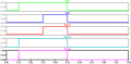
how do i getIf you want a digital output, you're going to need more than one transistor.
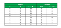
A half adder takes an XOR and an AND gate. A full adder can be implemented with two half adders and an OR gate.
Referring to a new article i have created this new full adder using diodes and resistors nowIf you want a digital output, you're going to need more than one transistor.
A half adder takes an XOR and an AND gate. A full adder can be implemented with two half adders and an OR gate.
https://hackaday.io/project/11860-diodes-only/log/52981-diode-full-adder
how do i get output in this?
Attachments
-
8.2 KB Views: 23
-
69.8 KB Views: 25
") circuit you could build a full adder using the LTspice standard digital gates.
circuit you could build a full adder using the LTspice standard digital gates.