ftdi usb-rs232-pcba with ATmega324P USART connection

Thread Starter

vhb

Joined Nov 19, 2015
6
Hi all,
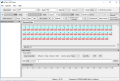
I have a very weird problem. I am using Codevision AVR to run the USART with ftdi usb-rs232-pcba. I have initialized every thing and using hTerm terminal and it works correctly. When I short circuit the Rx and Tx on ftdi usb-rs232-pcba and send something, receive it on the terminal but, I can't run it with micro.
C:
#include <mega324.h>
#include <delay.h>
#include <stdio.h>

int i;

// Declare your global variables here

#define DATA_REGISTER_EMPTY (1<<UDRE0)
#define RX_COMPLETE (1<<RXC0)
#define FRAMING_ERROR (1<<FE0)
#define PARITY_ERROR (1<<UPE0)
#define DATA_OVERRUN (1<<DOR0)

// Get a character from the USART1 Receiver
#pragma used+
char getchar1(void)
{
unsigned char status;
char data;
while (1)
      {
      while (((status=UCSR1A) & RX_COMPLETE)==0);
      data=UDR1;
      if ((status & (FRAMING_ERROR | PARITY_ERROR | DATA_OVERRUN))==0)
         return data;
      }
}
#pragma used-

// Write a character to the USART1 Transmitter
#pragma used+
void putchar1(char c)
{
while ((UCSR1A & DATA_REGISTER_EMPTY)==0);
UDR1=c;
}
#pragma used-

void main(void)
{
// Declare your local variables here

// Crystal Oscillator division factor: 1
#pragma optsize-
CLKPR=(1<<CLKPCE);
CLKPR=(0<<CLKPCE) | (0<<CLKPS3) | (0<<CLKPS2) | (0<<CLKPS1) | (0<<CLKPS0);
#ifdef _OPTIMIZE_SIZE_
#pragma optsize+
#endif

// Input/Output Ports initialization
// Port A initialization
// Function: Bit7=In Bit6=In Bit5=In Bit4=In Bit3=In Bit2=In Bit1=In Bit0=In
DDRA=(0<<DDA7) | (0<<DDA6) | (0<<DDA5) | (0<<DDA4) | (0<<DDA3) | (0<<DDA2) | (0<<DDA1) | (0<<DDA0);
// State: Bit7=T Bit6=T Bit5=T Bit4=T Bit3=T Bit2=T Bit1=T Bit0=T
PORTA=(0<<PORTA7) | (0<<PORTA6) | (0<<PORTA5) | (0<<PORTA4) | (0<<PORTA3) | (0<<PORTA2) | (0<<PORTA1) | (0<<PORTA0);

// Port B initialization
// Function: Bit7=In Bit6=In Bit5=In Bit4=In Bit3=In Bit2=In Bit1=In Bit0=In
DDRB=(0<<DDB7) | (0<<DDB6) | (0<<DDB5) | (0<<DDB4) | (0<<DDB3) | (0<<DDB2) | (0<<DDB1) | (1<<DDB0);
// State: Bit7=T Bit6=T Bit5=T Bit4=T Bit3=T Bit2=T Bit1=T Bit0=T
PORTB=(0<<PORTB7) | (0<<PORTB6) | (0<<PORTB5) | (0<<PORTB4) | (0<<PORTB3) | (0<<PORTB2) | (0<<PORTB1) | (0<<PORTB0);

// Port C initialization
// Function: Bit7=In Bit6=In Bit5=In Bit4=In Bit3=In Bit2=In Bit1=In Bit0=In
DDRC=(0<<DDC7) | (0<<DDC6) | (0<<DDC5) | (0<<DDC4) | (0<<DDC3) | (0<<DDC2) | (0<<DDC1) | (0<<DDC0);
// State: Bit7=T Bit6=T Bit5=T Bit4=T Bit3=T Bit2=T Bit1=T Bit0=T
PORTC=(0<<PORTC7) | (0<<PORTC6) | (0<<PORTC5) | (0<<PORTC4) | (0<<PORTC3) | (0<<PORTC2) | (0<<PORTC1) | (0<<PORTC0);

// Port D initialization
// Function: Bit7=In Bit6=In Bit5=In Bit4=In Bit3=In Bit2=In Bit1=In Bit0=In
DDRD=(0<<DDD7) | (0<<DDD6) | (0<<DDD5) | (0<<DDD4) | (0<<DDD3) | (0<<DDD2) | (0<<DDD1) | (0<<DDD0);
// State: Bit7=T Bit6=T Bit5=T Bit4=T Bit3=T Bit2=T Bit1=T Bit0=T
PORTD=(0<<PORTD7) | (0<<PORTD6) | (0<<PORTD5) | (0<<PORTD4) | (0<<PORTD3) | (0<<PORTD2) | (0<<PORTD1) | (0<<PORTD0);

// Timer/Counter 0 initialization
// Clock source: System Clock
// Clock value: Timer 0 Stopped
// Mode: Normal top=0xFF
// OC0A output: Disconnected
// OC0B output: Disconnected
TCCR0A=(0<<COM0A1) | (0<<COM0A0) | (0<<COM0B1) | (0<<COM0B0) | (0<<WGM01) | (0<<WGM00);
TCCR0B=(0<<WGM02) | (0<<CS02) | (0<<CS01) | (0<<CS00);
TCNT0=0x00;
OCR0A=0x00;
OCR0B=0x00;

// Timer/Counter 1 initialization
// Clock source: System Clock
// Clock value: Timer1 Stopped
// Mode: Normal top=0xFFFF
// OC1A output: Disconnected
// OC1B output: Disconnected
// Noise Canceler: Off
// Input Capture on Falling Edge
// Timer1 Overflow Interrupt: Off
// Input Capture Interrupt: Off
// Compare A Match Interrupt: Off
// Compare B Match Interrupt: Off
TCCR1A=(0<<COM1A1) | (0<<COM1A0) | (0<<COM1B1) | (0<<COM1B0) | (0<<WGM11) | (0<<WGM10);
TCCR1B=(0<<ICNC1) | (0<<ICES1) | (0<<WGM13) | (0<<WGM12) | (0<<CS12) | (0<<CS11) | (0<<CS10);
TCNT1H=0x00;
TCNT1L=0x00;
ICR1H=0x00;
ICR1L=0x00;
OCR1AH=0x00;
OCR1AL=0x00;
OCR1BH=0x00;
OCR1BL=0x00;

// Timer/Counter 2 initialization
// Clock source: System Clock
// Clock value: Timer2 Stopped
// Mode: Normal top=0xFF
// OC2A output: Disconnected
// OC2B output: Disconnected
ASSR=(0<<EXCLK) | (0<<AS2);
TCCR2A=(0<<COM2A1) | (0<<COM2A0) | (0<<COM2B1) | (0<<COM2B0) | (0<<WGM21) | (0<<WGM20);
TCCR2B=(0<<WGM22) | (0<<CS22) | (0<<CS21) | (0<<CS20);
TCNT2=0x00;
OCR2A=0x00;
OCR2B=0x00;

// Timer/Counter 0 Interrupt(s) initialization
TIMSK0=(0<<OCIE0B) | (0<<OCIE0A) | (0<<TOIE0);

// Timer/Counter 1 Interrupt(s) initialization
TIMSK1=(0<<ICIE1) | (0<<OCIE1B) | (0<<OCIE1A) | (0<<TOIE1);

// Timer/Counter 2 Interrupt(s) initialization
TIMSK2=(0<<OCIE2B) | (0<<OCIE2A) | (0<<TOIE2);

// External Interrupt(s) initialization
// INT0: Off
// INT1: Off
// INT2: Off
// Interrupt on any change on pins PCINT0-7: Off
// Interrupt on any change on pins PCINT8-15: Off
// Interrupt on any change on pins PCINT16-23: Off
// Interrupt on any change on pins PCINT24-31: Off
EICRA=(0<<ISC21) | (0<<ISC20) | (0<<ISC11) | (0<<ISC10) | (0<<ISC01) | (0<<ISC00);
EIMSK=(0<<INT2) | (0<<INT1) | (0<<INT0);
PCICR=(0<<PCIE3) | (0<<PCIE2) | (0<<PCIE1) | (0<<PCIE0);

// USART0 initialization
// USART0 disabled
UCSR0B=(0<<RXCIE0) | (0<<TXCIE0) | (0<<UDRIE0) | (0<<RXEN0) | (0<<TXEN0) | (0<<UCSZ02) | (0<<RXB80) | (0<<TXB80);

// USART1 initialization
// Communication Parameters: 8 Data, 1 Stop, No Parity
// USART1 Receiver: On
// USART1 Transmitter: On
// USART1 Mode: Asynchronous
// USART1 Baud Rate: 9600
UCSR1A=(0<<RXC1) | (0<<TXC1) | (0<<UDRE1) | (0<<FE1) | (0<<DOR1) | (0<<UPE1) | (0<<U2X1) | (0<<MPCM1);
UCSR1B=(0<<RXCIE1) | (0<<TXCIE1) | (0<<UDRIE1) | (1<<RXEN1) | (1<<TXEN1) | (0<<UCSZ12) | (0<<RXB81) | (0<<TXB81);
UCSR1C=(0<<UMSEL11) | (0<<UMSEL10) | (0<<UPM11) | (0<<UPM10) | (0<<USBS1) | (1<<UCSZ11) | (1<<UCSZ10) | (0<<UCPOL1);
UBRR1H=0x00;
UBRR1L=0x4D;

// Analog Comparator initialization
// Analog Comparator: Off
// The Analog Comparator's positive input is
// connected to the AIN0 pin
// The Analog Comparator's negative input is
// connected to the AIN1 pin
ACSR=(1<<ACD) | (0<<ACBG) | (0<<ACO) | (0<<ACI) | (0<<ACIE) | (0<<ACIC) | (0<<ACIS1) | (0<<ACIS0);
ADCSRB=(0<<ACME);
// Digital input buffer on AIN0: On
// Digital input buffer on AIN1: On
DIDR1=(0<<AIN0D) | (0<<AIN1D);

// ADC initialization
// ADC disabled
ADCSRA=(0<<ADEN) | (0<<ADSC) | (0<<ADATE) | (0<<ADIF) | (0<<ADIE) | (0<<ADPS2) | (0<<ADPS1) | (0<<ADPS0);

// SPI initialization
// SPI disabled
SPCR=(0<<SPIE) | (0<<SPE) | (0<<DORD) | (0<<MSTR) | (0<<CPOL) | (0<<CPHA) | (0<<SPR1) | (0<<SPR0);

// TWI initialization
// TWI disabled
TWCR=(0<<TWEA) | (0<<TWSTA) | (0<<TWSTO) | (0<<TWEN) | (0<<TWIE);

while (1)
      {
      PORTB.0=1;
      delay_ms(100);
      PORTB.0=0;
      delay_ms(100);
      i = 10;
      printf("%d",i);

      }
}
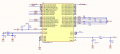
I wrote this simple program but receive nothing. PortB is just connected to a LED that I understands it is working correctly. I have double checked everything, baud rate, parity, stop bit and .... but no answer. Rx of ftdi usb-rs232-pcba has been connected to Tx of micro with same grounding. Can somebody help me?

Moderator edit: added code tags.
 

Attachments

MrChips

Joined Oct 2, 2009
30,810
1) Explain what this does:

(0<<PORT7)

2) Explain what is

DATA_REGISTER_EMPTY

You have way too many errors in your code.

Start off by writing a simple program to make an LED flash.
 

Thread Starter

vhb

Joined Nov 19, 2015
6
1) Explain what this does:

(0<<PORT7)

2) Explain what is

DATA_REGISTER_EMPTY

You have way too many errors in your code.

Start off by writing a simple program to make an LED flash.
Now the program turns on and off one LED (100ms) and I also checked the ADC by a separate prog and it is working. initialization has been done by Codevision.
 

MrChips

Joined Oct 2, 2009
30,810
Do you have an oscilloscope?

Try modifying the while( ) loop in your main program to this;
C:
while (1)
      {
      PORTB.0=1;
      delay_ms(100);
      PORTB.0=0;
      delay_ms(100);
      putchar1('U');  
      }
 

Thread Starter

vhb

Joined Nov 19, 2015
6
Do you have an oscilloscope?

Try modifying the while( ) loop in your main program to this;
C:
while (1)
      {
      PORTB.0=1;
      delay_ms(100);
      PORTB.0=0;
      delay_ms(100);
      putchar1('U'); 
      }
Great worked, but what was the problem? :( why it worked with putchar1('U') but not with putchar('U')?
 

MrChips

Joined Oct 2, 2009
30,810
1) If you want to call putchar( ) then change all the names putchar1 to putchar.

2) printf( ) is a C library function. You need to find out how it works and how to redirect the output to your putchar( ).

3) Remove while(1) in getchar1( ).
 

Thread Starter

vhb

Joined Nov 19, 2015
6
1) If you want to call putchar( ) then change all the names putchar1 to putchar.

2) printf( ) is a C library function. You need to find out how it works and how to redirect the output to your putchar( ).

3) Remove while(1) in getchar1( ).
Thanks but I called the stdio.h which is the library for printf! The question is why it does not work.
 

MrChips

Joined Oct 2, 2009
30,810
2) printf( ) is a C library function. You need to find out how it works and how to redirect the output to your putchar( ).

Do you understand what I wrote?

printf( ) is a C library function.
stdio.h does not know where to send the output. You need to tell putchar( ) where to send the output.
Look into stdio.h and see if there is a getchar( ) and putchar( ) function.

You need to read the CodeVision manual to see how to redirect the input and output.
 

Thread Starter

vhb

Joined Nov 19, 2015
6
Hi,
I switched from USART1 to USART0 with some wiring. Then I can access to all the functions. I also could run printf() and also changed the printf() to int function. see the attached. But still sending weird things.

Code:
#include <mega324.h>

// Declare your global variables here

// Standard Input/Output functions
#include <stdio.h>
#include <delay.h>

int a=5,b=10,c=15;
char i,p[10];

void main(void)
{
// Declare your local variables here

// Crystal Oscillator division factor: 1
#pragma optsize-
CLKPR=(1<<CLKPCE);
CLKPR=(0<<CLKPCE) | (0<<CLKPS3) | (0<<CLKPS2) | (0<<CLKPS1) | (0<<CLKPS0);
#ifdef _OPTIMIZE_SIZE_
#pragma optsize+
#endif

// Input/Output Ports initialization
// Port A initialization
// Function: Bit7=In Bit6=In Bit5=In Bit4=In Bit3=In Bit2=In Bit1=In Bit0=In
DDRA=(0<<DDA7) | (0<<DDA6) | (0<<DDA5) | (0<<DDA4) | (0<<DDA3) | (0<<DDA2) | (0<<DDA1) | (0<<DDA0);
// State: Bit7=T Bit6=T Bit5=T Bit4=T Bit3=T Bit2=T Bit1=T Bit0=T
PORTA=(0<<PORTA7) | (0<<PORTA6) | (0<<PORTA5) | (0<<PORTA4) | (0<<PORTA3) | (0<<PORTA2) | (0<<PORTA1) | (0<<PORTA0);

// Port B initialization
// Function: Bit7=In Bit6=In Bit5=In Bit4=In Bit3=In Bit2=In Bit1=In Bit0=In
DDRB=(0<<DDB7) | (0<<DDB6) | (0<<DDB5) | (0<<DDB4) | (0<<DDB3) | (0<<DDB2) | (0<<DDB1) | (0<<DDB0);
// State: Bit7=T Bit6=T Bit5=T Bit4=T Bit3=T Bit2=T Bit1=T Bit0=T
PORTB=(0<<PORTB7) | (0<<PORTB6) | (0<<PORTB5) | (0<<PORTB4) | (0<<PORTB3) | (0<<PORTB2) | (0<<PORTB1) | (0<<PORTB0);

// Port C initialization
// Function: Bit7=In Bit6=In Bit5=In Bit4=In Bit3=In Bit2=In Bit1=In Bit0=In
DDRC=(0<<DDC7) | (0<<DDC6) | (0<<DDC5) | (0<<DDC4) | (0<<DDC3) | (0<<DDC2) | (0<<DDC1) | (0<<DDC0);
// State: Bit7=T Bit6=T Bit5=T Bit4=T Bit3=T Bit2=T Bit1=T Bit0=T
PORTC=(0<<PORTC7) | (0<<PORTC6) | (0<<PORTC5) | (0<<PORTC4) | (0<<PORTC3) | (0<<PORTC2) | (0<<PORTC1) | (0<<PORTC0);

// Port D initialization
// Function: Bit7=In Bit6=In Bit5=In Bit4=In Bit3=In Bit2=In Bit1=In Bit0=In
DDRD=(0<<DDD7) | (0<<DDD6) | (0<<DDD5) | (0<<DDD4) | (0<<DDD3) | (0<<DDD2) | (0<<DDD1) | (0<<DDD0);
// State: Bit7=T Bit6=T Bit5=T Bit4=T Bit3=T Bit2=T Bit1=T Bit0=T
PORTD=(0<<PORTD7) | (0<<PORTD6) | (0<<PORTD5) | (0<<PORTD4) | (0<<PORTD3) | (0<<PORTD2) | (0<<PORTD1) | (0<<PORTD0);

// Timer/Counter 0 initialization
// Clock source: System Clock
// Clock value: Timer 0 Stopped
// Mode: Normal top=0xFF
// OC0A output: Disconnected
// OC0B output: Disconnected
TCCR0A=(0<<COM0A1) | (0<<COM0A0) | (0<<COM0B1) | (0<<COM0B0) | (0<<WGM01) | (0<<WGM00);
TCCR0B=(0<<WGM02) | (0<<CS02) | (0<<CS01) | (0<<CS00);
TCNT0=0x00;
OCR0A=0x00;
OCR0B=0x00;

// Timer/Counter 1 initialization
// Clock source: System Clock
// Clock value: Timer1 Stopped
// Mode: Normal top=0xFFFF
// OC1A output: Disconnected
// OC1B output: Disconnected
// Noise Canceler: Off
// Input Capture on Falling Edge
// Timer1 Overflow Interrupt: Off
// Input Capture Interrupt: Off
// Compare A Match Interrupt: Off
// Compare B Match Interrupt: Off
TCCR1A=(0<<COM1A1) | (0<<COM1A0) | (0<<COM1B1) | (0<<COM1B0) | (0<<WGM11) | (0<<WGM10);
TCCR1B=(0<<ICNC1) | (0<<ICES1) | (0<<WGM13) | (0<<WGM12) | (0<<CS12) | (0<<CS11) | (0<<CS10);
TCNT1H=0x00;
TCNT1L=0x00;
ICR1H=0x00;
ICR1L=0x00;
OCR1AH=0x00;
OCR1AL=0x00;
OCR1BH=0x00;
OCR1BL=0x00;

// Timer/Counter 2 initialization
// Clock source: System Clock
// Clock value: Timer2 Stopped
// Mode: Normal top=0xFF
// OC2A output: Disconnected
// OC2B output: Disconnected
ASSR=(0<<EXCLK) | (0<<AS2);
TCCR2A=(0<<COM2A1) | (0<<COM2A0) | (0<<COM2B1) | (0<<COM2B0) | (0<<WGM21) | (0<<WGM20);
TCCR2B=(0<<WGM22) | (0<<CS22) | (0<<CS21) | (0<<CS20);
TCNT2=0x00;
OCR2A=0x00;
OCR2B=0x00;

// Timer/Counter 0 Interrupt(s) initialization
TIMSK0=(0<<OCIE0B) | (0<<OCIE0A) | (0<<TOIE0);

// Timer/Counter 1 Interrupt(s) initialization
TIMSK1=(0<<ICIE1) | (0<<OCIE1B) | (0<<OCIE1A) | (0<<TOIE1);

// Timer/Counter 2 Interrupt(s) initialization
TIMSK2=(0<<OCIE2B) | (0<<OCIE2A) | (0<<TOIE2);

// External Interrupt(s) initialization
// INT0: Off
// INT1: Off
// INT2: Off
// Interrupt on any change on pins PCINT0-7: Off
// Interrupt on any change on pins PCINT8-15: Off
// Interrupt on any change on pins PCINT16-23: Off
// Interrupt on any change on pins PCINT24-31: Off
EICRA=(0<<ISC21) | (0<<ISC20) | (0<<ISC11) | (0<<ISC10) | (0<<ISC01) | (0<<ISC00);
EIMSK=(0<<INT2) | (0<<INT1) | (0<<INT0);
PCICR=(0<<PCIE3) | (0<<PCIE2) | (0<<PCIE1) | (0<<PCIE0);

// USART0 initialization
// Communication Parameters: 8 Data, 1 Stop, No Parity
// USART0 Receiver: On
// USART0 Transmitter: On
// USART0 Mode: Asynchronous
// USART0 Baud Rate: 9600
UCSR0A=(0<<RXC0) | (0<<TXC0) | (0<<UDRE0) | (0<<FE0) | (0<<DOR0) | (0<<UPE0) | (0<<U2X0) | (0<<MPCM0);
UCSR0B=(0<<RXCIE0) | (0<<TXCIE0) | (0<<UDRIE0) | (1<<RXEN0) | (1<<TXEN0) | (0<<UCSZ02) | (0<<RXB80) | (0<<TXB80);
UCSR0C=(0<<UMSEL01) | (0<<UMSEL00) | (0<<UPM01) | (0<<UPM00) | (0<<USBS0) | (1<<UCSZ01) | (1<<UCSZ00) | (0<<UCPOL0);
UBRR0H=0x00;
UBRR0L=0x4D;

// USART1 initialization
// USART1 disabled
UCSR1B=(0<<RXCIE1) | (0<<TXCIE1) | (0<<UDRIE1) | (0<<RXEN1) | (0<<TXEN1) | (0<<UCSZ12) | (0<<RXB81) | (0<<TXB81);

// Analog Comparator initialization
// Analog Comparator: Off
// The Analog Comparator's positive input is
// connected to the AIN0 pin
// The Analog Comparator's negative input is
// connected to the AIN1 pin
ACSR=(1<<ACD) | (0<<ACBG) | (0<<ACO) | (0<<ACI) | (0<<ACIE) | (0<<ACIC) | (0<<ACIS1) | (0<<ACIS0);
ADCSRB=(0<<ACME);
// Digital input buffer on AIN0: On
// Digital input buffer on AIN1: On
DIDR1=(0<<AIN0D) | (0<<AIN1D);

// ADC initialization
// ADC disabled
ADCSRA=(0<<ADEN) | (0<<ADSC) | (0<<ADATE) | (0<<ADIF) | (0<<ADIE) | (0<<ADPS2) | (0<<ADPS1) | (0<<ADPS0);

// SPI initialization
// SPI disabled
SPCR=(0<<SPIE) | (0<<SPE) | (0<<DORD) | (0<<MSTR) | (0<<CPOL) | (0<<CPHA) | (0<<SPR1) | (0<<SPR0);

// TWI initialization
// TWI disabled
TWCR=(0<<TWEA) | (0<<TWSTA) | (0<<TWSTO) | (0<<TWEN) | (0<<TWIE);

while (1)
      {
      PORTB.0 = 1;
      delay_ms(100);
      PORTB.0 = 0;
      delay_ms(100);
      //i = 5;
      printf("%d",a);
      //putchar(i); 
      //sprintf(p,"Time %u: %u: %u",a,b,c);
      //puts(p);

      }
}
By the way MrChips, It is not necessary to get angry. It is problem solving.
 

Attachments

Top