Fridge Door Open Alarm Project Advice

Thread Starter

ajhoward

Joined Nov 16, 2011
46
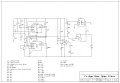
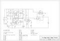
This is my Fridge Door Open Alarm circuit, but I need some advice on Q1, Q2 and Q5. I need Q1 & Q2 to hold the reset pin to low when the reed switch is open and to high when the reed switch is closed. Q5 is meant to connect power when the reed switch is closed, power down the circuit after a short delay when the reed switch is opened.

Please disregard the parts list, and missing component ids as I have chopped and changed a few things and am still working out the design.
 

Attachments

sheldons

Joined Oct 26, 2011
613
With your reed switch you may have contact bounce problems....heres a similar circuit that was designed for somebody a while back-ive not included the values for the osc side of it as you may(or may not) want a pulsed tone ....
 

Attachments

thatoneguy

Joined Feb 19, 2009
6,359
Can you simply power up a delay when the door is opened, and after 1 minute, the buzzer goes off?

When the door is fully closed again, power is removed, and the cycle starts over.

For the 9V Supply, 9V batteries only have roughly 300mAH of power, so they go dead quickly when running higher current draw circuits like buzzers and relays. I'd suggest a 6V supply via 4 AA's in a holder, or a 9VDC wall wart. AA Batteries have 2750mAH storage, and a switching type wall wart power supply draws no current when not in use (A transformer type dissipates about 1W in idle heat).
 

Thread Starter

ajhoward

Joined Nov 16, 2011
46
Yeah, that transistor circuit will do the trick. The delay at when the door is opened is working fine the 556 timer has been tested on the breadboard is is working fine.

I guess if the alarm is activated and the door is shut the circuit will be powered down, which would stop the alarm. So I won't any extra transistors to hold the reset pin. None the less, this is more than just a project to tell me when one of the kids have left the door open. Trying to learn at the same time. That buzzer circuit that you posted is giving me a headache trying to remember the highs and lows, and what gate is activated and which is not. Will that capacitor across the reed switch stop the bounce?

The point you made oneguy about the 9V is a useful point that I will definitely use, because I would like to get maybe 6 months from the batteries if possible or close enough to it.

I'll post the completed circuit once I get it up and running.
 

Thread Starter

ajhoward

Joined Nov 16, 2011
46
Try this .............
I tried adopting this circuit into mine with output connected to pin 10 of IC1 and the input connected to S1, but it seems to be doing the opposite of what I need (high when the switch is open and low when the switch is closed), I don't think the plan with using it for the reset pin will work anyway, because I already have Q1 attached to pin 10 that hold its low until the monostable times out. When I connect the output of your circuit to the reset pin just stays high. If disconnect the output and connect the input to my circuit and check the output that's when I see the output change like as I said before.

I was thinking though if I could make your circuit work in reverse, I could use to drive the A210DN. I can't seem to get that to work correctly is the output supposed to go in series with the positive line, or is one side supposed to go to earth and the other to drive the rest of the circuit?
 

Attachments

Thread Starter

ajhoward

Joined Nov 16, 2011
46
With your reed switch you may have contact bounce problems....heres a similar circuit that was designed for somebody a while back-ive not included the values for the osc side of it as you may(or may not) want a pulsed tone ....
Does this circuit provide a delay before the alarm goes off?. Yes, I do want a pulsed tone.
 

Yako

Joined Nov 24, 2011
245
You wanna do me a favour and explain the requirements of all those parts? You should be calculating resistors, and not simply using VRs and Zeners for Vrefs.

Bit confused :confused:
 

Thread Starter

ajhoward

Joined Nov 16, 2011
46
You wanna do me a favour and explain the requirements of all those parts? You should be calculating resistors, and not simply using VRs and Zeners for Vrefs.

Bit confused :confused:
Yeah. How it works is, IC1A forms a monostable timer that is triggered by the NO Reed Switch S1. When S1 is closed the output of IC1A goes high which turns on Q1 which holds the reset pin of IC1B a astable tone generator to ground preventing the output from going high and sounding the buzzer.

After the set timeout period has passed, IC1As output will go low, making the reset pin go high, allowing the astable tone generator to sound the alarm.

IC2 forms a battery tester that will light the LED when the battery voltage drops to a set level determined by VR2 and ZD1.

IC3 is a solid state relay that is meant to power down everything except IC3 and Q3 when the door is closed and wake everything up again when the door is opened to begin the process again.

This is still in early stages, I may or may not use the variable resistors. I did calculate the resistor values, just added here for practicality.
 

Yako

Joined Nov 24, 2011
245
I just see it all as a cost thing dude.

I mean, a resistor is like usd 0.001 if buying a few pcs, whereas a trimpot is 20+ x the cost. Zener diodes are not cheap either, and they are not thermally stable, also waste power because they require forward biasing of 5mA+ to sustain regulation.

To me it looks like you are using a machinegun to kill a rat if you know what I am talking about.
 

Thread Starter

ajhoward

Joined Nov 16, 2011
46
Yeah, but machine guns are so much more fun than a pee shooter. :)

Good point about the zener diode though. Quite interested in the circuit sheldon posted with the nand gates. Looks more simple and efficient than what I have.
 

Yako

Joined Nov 24, 2011
245
Yeah, but machine guns are so much more fun than a pee shooter. :)
Usually when I engineer something I make a dot-point form list of the requirements. Otherwise you'll just drive yourself insane.

i.e.

  • If sensor detects door open more than (n) period then switch on buzzer
  • If (n) period expires then cease ...
  • Reset (n) period when door closes
  • And so on ...
Then you decompose this down further into component form.

All those parts that you have I don't geddit :confused:
 

Yako

Joined Nov 24, 2011
245
Too hard to go straight to schematic.

Also, normal people can read block diagrams. So this way the engineer can collaborate with non-technical people.
 

sheldons

Joined Oct 26, 2011
613
well if you check the schematic,with the reed switch open the first npn transistor will hold the pnp transistors base low,turning that transistors emmiter high switching on the final npn transistor on so the collector will be low......its the opposite when the switch is closed test it on its own....ill sort the component values for you later for the other schematic......
 
Top