Four resistor bias circuit help!

Thread Starter

DavS13

Joined Jun 16, 2014
21
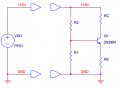
Below is the following circuit. It is an npn BJT in forward active mode.
R2 = 8k ohm
R1 = 1.4k ohm
Rc = 5k ohm
Re = 1k ohm

Vb = 1.512V
Ve = 0.876V
Vc = 5.512V

These voltages are actual values measured in the lab. Im trying to find ib, ic, and ie, all terminal currents.
This is what I did:

Ie = Ve/Re = 0.876mA
Ic = (10-Vc)/Rc = 0.8976mA
Ib = Ie - Ic = -21 micro A

How does this make any sense???
I need to find the terminal currents and find the gain, beta. Are the terminal currents different from the currents through the resistors?
I feel like I am doing something very wrong here, please help!

upload_2014-10-17_22-40-45.png
 

Attachments

Last edited:

JoeJester

Joined Apr 26, 2005
4,390
Couple of quick questions ....

1. Are the resistance values "measured"?
2. Are you sure that Rc is 50k?

No, it does not make any sense.
 
Last edited:

jjw

Joined Dec 24, 2013
823
The base voltage can't be higher than the voltage from voltage divider R1/R2 ~1.49V
Are the resistors measured?
 

studiot

Joined Nov 9, 2007
4,998
Well Ib is negative because your equation assumes it in the same direction as Ie that is leaving the emitter/base node (KCL). Of course conventional current is inward at this node.

This would make beta (Ic/Ib) equal to 42.7, reasonable for this setup.

Base voltage at 0.636V above the emitter seems reasonable for an 'on' transistor.
This would make your readings seem reasonable.

However as jjw points out the base voltage reading is apparantly too high, because it is above the potential divider set by R1 and dR2, but worse the voltage across R1 should actually be lower than 1.49 because R1 is shunted by beta times Re.

So I deduce that one or both of R1 and R2 are in error.

8k and 1k4 are strange values to choose, where did they come from?
 
Last edited:

JoeJester

Joined Apr 26, 2005
4,390
Sorry guys its 5K! I'v edited it. No, resistance values are not measured the Vb, Ve, and Vc values are
Only two of the resistors you've mentioned are standard values. What series are you using?
 

Thread Starter

DavS13

Joined Jun 16, 2014
21
The objective was to design a voltage divider of R2 amd R1 such that the base is at 1.5V. Emitter voltage will then be about 0.7V less than this, so we had to choose Re so that the emitter current is about 0.8mA. Then I was to choose a value for Rc to drop the collector voltage down to 6V, while maintaining a 0.8mA collector current. This was the objective for this lab, the resistors I chose seem to work fine theoretically for these specs. Are you saying maybe I accidentally put in the wrong resistors? Can you tell me what is the result I should have got and where my error is if you can?
Also I was told to measure the current through the resistors and also find the collector, emitter, and base currents. How are the resistor currents different from these? Maybe the question was worded weirdly.
 

Alec_t

Joined Sep 17, 2013
14,280
Have you allowed for resistor tolerance? The actual value will be different from the marked or theoretical value. You need to measure the actual resistor values.
 

Alec_t

Joined Sep 17, 2013
14,280
it wouldn't make a difference this large
Depends on the tolerance. Your calculated collector and emitter currents differ by only 2%, with Ie being < Ic. Ie should really be > Ic. A 4% shift would correct this. Resistors commonly used have a 10% tolerance. What tolerance do your resistors have?
 
Top