Four engine alarm leds share one alarm buzzer-possible schematics.

Thread Starter

AlunW

Joined Feb 5, 2016
6
Hi there,
This an embarrassingly simple question, but I'm stumped at the moment.
I have four normally open alarm switches on a marine Diesel engine.
They all are earthed and supplied with 12v when the ignition is switched on.
When water temp rises or oil pressure falls etc. the switches Close and the alarm is active.(led lights up, buzzer buzzes).
The original alarm panel and circuitry is destroyed.
I intend to create my own custom alarm panel with four 12v leds, a buzzer, and a silencing or reset switch.
It's pretty simple to wire each alarm and led to the ignition switch, but the logic for sharing one piezo buzzer between the four alarms defeats me.
Is it as simple as just wiring the buzzer in series with the leds?
Or does it have to be in parallel with the 4 leds.
This is insanely simple compared to most of the stuff on this forum.
Thanks in advance for any assistance.
Regards
Alun
 

dl324

Joined Mar 30, 2015
18,412
Welcome to AAC!
  1. Do the LEDs have built-in current limiting resistors?
  2. What current do you want in the LEDs?
  3. What are the resistance, voltage, and current requirements of the buzzer?
  4. How are the switches reset?
  5. Do you want to implement this without any logic gates (integrated or discrete)?
 

Thread Starter

AlunW

Joined Feb 5, 2016
6
Welcome to AAC!
  1. Do the LEDs have built-in current limiting resistors?
  2. What current do you want in the LEDs?
  3. What are the resistance, voltage, and current requirements of the buzzer?
  4. How are the switches reset?
  5. Do you want to implement this without any logic gates (integrated or discrete)?
Hi there thanks for replying.

1. Yes they work great with 12 v across them, not sure what resistor is built in. But I can see one there shrink wrapped on.

2. I suppose they draw around the 20mA....

3. The buzzer is nominally 12v but I believe it works over much greater range, say 5-25v.....draws about 20-30 mA

4. I was simply going to put a switch between the ignition switch and the alarm system.
It's not elegant but if the alarm actually goes off I'll have "bigger fish to fry" while I sort that issue out.
I'm open to a more elegant reset idea, but given I'm stuck on this bit....

5. Correct. Switches and relays, maybe diodes I'd necessary.

Thanks again for your reply.
Regards
Alun
 

jpanhalt

Joined Jan 18, 2008
11,087
1) When you disable the buzzer, do you want the LED for that sensor to stay on until the problem is fixed? ( I assume yes.)
2) If a second sensor creates an alarm, I assume you want its LED to light too. Do you want the buzzer to go off again or does it matter?

John
 

Thread Starter

AlunW

Joined Feb 5, 2016
6
1) When you disable the buzzer, do you want the LED for that sensor to stay on until the problem is fixed? ( I assume yes.)
2) If a second sensor creates an alarm, I assume you want its LED to light too. Do you want the buzzer to go off again or does it matter?

John
Hi John,

1. Yes, I would like the led to stay on until the engine alarm switch re-opens.

2. Yes I would like the buzzer to go off for a second alarm, but I accept it can't go off while my inelegant alarm system off switch is being used. I would expect a buzzer when I switched the system back on though.

3. At that point my interest in boating would decline dramatically :-(

Thanks for your interest
Regards
Alun
 

Thread Starter

AlunW

Joined Feb 5, 2016
6
Do you want to implement this without any logic gates (integrated or discrete)?
I've thought about this a bit more.
I probably wouldn't fully understand a circuit that was based around these.....but if it was a better solution I could almost certainly build what was required.

Just to clarify.
Regards
Alun
 

crutschow

Joined Mar 14, 2008
38,587
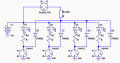
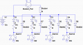
Here's my take on a simple circuit to do what you want.
It uses one diode on each switch to isolate the buzzer so that the buzzer activates when any of the engine sensor contacts close but only the related LED Lights.

upload_2018-8-11_23-30-11.png
 

Thread Starter

AlunW

Joined Feb 5, 2016
6
Here's my take on a simple circuit to do what you want.
It uses one diode on each switch to isolate the buzzer so that the buzzer activates when any of the engine sensor contacts close but only the related LED Lights.

View attachment 157944
Of course! Thank you so much.
And thank you to the other posters who helped me clarify what I really needed.

I had to use cut and paste into a word doc to get the diagram up a bit in size.
It doesn't seem to want to load as a pdf or a "full sized version".
But thats no problem.

I'll start building this later this week and will post a picture of the completed work.
Thanks again.
Regards
Alun
 

olphart

Joined Sep 22, 2012
125
Kudos to Crutschow: a simple wired-OR.

PS, I'll sometimes describe methods that I can't post a schematic of, because they're part of a product not owned by me.
 

Thread Starter

AlunW

Joined Feb 5, 2016
6
Just a quick update and thank you.
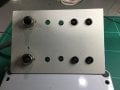
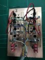
I built the circuit as shown above...almost!
Hopefully pics are attached. Still building when pics taken.
The physical aspects of the task were far more demanding than the soldering side
Enclosure, space constraints, wiring sizes, connectors and on and on.
And obviously the panel is set up for two engines, but each side operates completely independently, powered by the appropriate engines key switch
The switches I have used simply turn the buzzer off while appropriate marine type activity occurs to fix the issue!!!!
I'll label the leds when I get hold of a dymo or suchlike.
Anyway it works fine and is a big improvement in the previous Cummins system.
Thanks again for your assistance.
regards
Alun
.IMG_1288.JPG

IMG_1287.JPG
 
Top