FM Radio

Thread Starter

Homebrew1964

Joined Nov 22, 2024
192
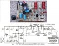
Is it possible to build a working FM radio receiver on stripboard? i have just built 2 simple circuits that i found online and neither worked, all i can hear is hissing and i'm wondering if i need to go to the trouble of making a PCB or if there is some other reason why these circuits arn't working? i can't/wont post the circuits due to copyright laws but they are simple one and two transistor designs.
 

meth

Joined May 21, 2016
304
PCB would be definitely better, solid ground plane is very important in low signal audio applications, not to mention FM frequencies... but if hissing is all you hear you might have another problem. PCB should improve sound quality by far but you might be doing something else wrong. I am not radio transmissions expert but without some details like your circuit and the antenna you are using, we cant tell more. So some schematic and also picture of your setup would be nice.
 
Last edited:

Thread Starter

Homebrew1964

Joined Nov 22, 2024
192

Audioguru again

Joined Oct 21, 2019
6,826
Here is my 3 transistors FM radio transmitter schematic. Its output power (about 70mW) is high enough to cause illegal interference to a radio station's frequency because its range is about 2km to a sensitive radio. It produces low distortion and a hifi bandwidth. Its pre-emphasis matches the de-emphasis of an FM radio. I built it on stripboard.
 

Attachments

MisterBill2

Joined Jan 23, 2018
27,519
The most likely cause of the receiver "not working right" is that it is tuned to the wrong frequency. The tuned circuit was done with a different build style and so the capacitance was different. So your receiver is probably not tuned to where you want it tuned.
 

sparky 1

Joined Nov 3, 2018
1,218
The RF components can mount on Vero. But the design should not be limited to strip board.
The resonant components that are sensitive hand capacitance benefit from larger section of copper ground plane.

Looking at PCBs examples that use ICs such as BA1417, KT9306, RD5807 the location and ground planes of external parts
often times can mean the difference between good or excellent. The field strength and audio quality is sometimes lacking by
not following practical guidelines. Try not to go from theory to design without avoiding many common mistakes.

It begins with a schematic, paper, pencil and a good eraser. Going from schematic is focusing on the islands of copper
where the through hole components mount that are not resonant and can use vero. The resonant parts do matter.
By sweeping resonant sections I found that the coils supported and epoxied, the rigidity improved frequency stability
and the ground plane improved the performance. FM frequency modulation with very small signals can sound alright
when you don't reinvent the wheel.
 

MisterBill2

Joined Jan 23, 2018
27,519
Back about 1962 there was a design for a one compactron tube FM receiver. It was indeed a regenerative detector type, with no RF stage to reduce emissions. It would disrupt FM reception of every FM radio in the house. AND with only one tuned circuit it was not very selective. It is a poor choice project even if it works perfectly.
 

sparky 1

Joined Nov 3, 2018
1,218
It is possible to measure FM modulation using SDR software. SDR play SDR RSD is made by repurposing RTL SDR dongle.
The spectrum analyser's cursors and markers and it's TCXO 0.5ppm, the step attenuator. The excel program also fine tuning.
The approach using an icom tranceiver is shown as good radio procedure, But SDR modulation and more videos on that are out there,
A little math allows experimenter/engineer to adjust modulation precisely. Have fun, go for high quality audio reception and clean spectrum.

Both follow same Bessel Null and FM deviation measurements given. The SDR is close enough, if directions are followed.
A real spec analyzer is faster, but having the nice full screen FFT next to the oscilloscope unclutters the scope.
 
Last edited:

crutschow

Joined Mar 14, 2008
38,507
I built this one-triode-tube regenerative FM receiver way back in the 60's and it worked reasonably well to pick up local FM stations.

Think I still have in somewhere in my pile of junk.

1737428129983.png
 
Last edited:

MisterBill2

Joined Jan 23, 2018
27,519
I built this one-triode-tube regenerative FM receiver way back in the 60's and it worked reasonably well to pick up local FM stations.

Think I still have in somewhere in my pile of junk.

View attachment 340842
Certainly that circuit can work as a reasonable FM broadcast receiver. AND, if you increase the B+ to about 250 volts, you can feed a few volts of audio into the "audio output" line and have a "fair" quality AM/FM transmitter. Not legally, but fairly effective with a good antenna.
 
Top