FM Pre-Emphasis and De-Emphasis - conflicting and impossible specifications

Thread Starter

retiredEE

Joined Nov 14, 2019
13
I am attempting to quantify specifications for the proper pre-emphasis and de-emphasis of transmitted and received audio respectively relative to communications radios vs broadcast radios.
My investigation has led to contradictory and incomplete information and so I turn to you all.

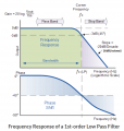
I find a standard of time constant of 75usec, 3db point at 2123 Hz and 6 db/octave is often stated on Internet sites with a single pole filter circuit diagram as the example of the filter. The 1974 Radio Amateur's Handbook only give the filter with no specifics on the characteristics.
The 1995 and 2001 Handbooks show filter schematics sporting time constants of 1 msec! This is 13.3 times longer than the 1974 Handbook.
The 2008 handbook doesn't even acknowledge that pre-emphasis and de-emphasis exists much less give any details of it.
So, here are my issues:
1. db ... the "standard" says 6 db/octave. Is this db as in 10*log(P2/P1) or db as in 20*log(V2/V1)?
2. If I simulate, hand calculate or build and measure (I've done all three of these) a single pole RC filter such as the one that is ubiquitously presented, I will not EVER get 6db/octave even if I consider it as dbV and CERTAINLY if I consider it db (power). Physics will not let me. So, either the 6 db/octave is bogus OR we are talking about a multi-pole filter to achieve this.
3. Will the real time constant PLEASE stand up? I see 75 usec and I see 1 millisecond. 75 usec seems to be more believable, but ARRL's Radio Amateur's Handbook is hard to ignore. Why the change from the 1974 Handbook to the 1995 Handbook?
 

Thread Starter

retiredEE

Joined Nov 14, 2019
13
The 1995 and 2001 Handbooks give a capacitor value of "0.1". If we assume 0.1uF, then the time constant is 1 msec. If we assume this is 0.1 F, then it is 1000 seconds. They also use 1 H inductor and a 1 K resistor. This is VERY clear and the LR time constant is undoubtedly 1000 seconds! So, this gives credence to believing the capacitor is intended to be 0.1 F, not 0.1 uF. Funky!
 

Thread Starter

retiredEE

Joined Nov 14, 2019
13
PERFECT! Why this didn't come up in any of my searches is a mystery. I have spent many hours at this so far and just never found this. What surprised me is what the Radio Amateur's Handbook had ... 1000 second time constant....yeah, 1,000 seconds! 10K resistor and 0.1F capacitor or a 1H inductor and a 1K resistor in both the 1995 and 2001 edition. I am assuming 1996, 1997, 1998, 1999 and 2000 editions also.
 

Audioguru again

Joined Oct 21, 2019
6,673
One RC always produces a slope of 6dB per octave. +6dB is double the voltage, -6dB is half the voltage.
75us pre-emphasis and de-emphasis were used originally a long time ago for FM radio and TV to reduce noise picked up for hifi. Later, when Europe began FM radio, they used 50us to reduce high audio frequency distortion. Old microphones and record players could not produce the high frequencies but new ones did.

Communications are far from being hifi which is why a common phrase in communications is, "What? What did you say?" over and over. Communications have a muffled frequency response that kills the important consonants in speech, producing only vowels (growls, grunts and groans).
 

Thread Starter

retiredEE

Joined Nov 14, 2019
13
One RC always produces a slope of 6dB per octave. +6dB is double the voltage, -6dB is half the voltage.
75us pre-emphasis and de-emphasis were used originally a long time ago for FM radio and TV to reduce noise picked up for hifi. Later, when Europe began FM radio, they used 50us to reduce high audio frequency distortion. Old microphones and record players could not produce the high frequencies but new ones did.

Communications are far from being hifi which is why a common phrase in communications is, "What? What did you say?" over and over. Communications have a muffled frequency response that kills the important consonants in speech, producing only vowels (growls, grunts and groans).
Let's do the math ...
Vout = Vin * Rout/(Rin + Rout) where Rout is actually Xc = 1/(2*pi*f*C)
If the frequency doubles, the value of Xc halves. This is going up one octave.
Let's choose Rin = 10K.
And let's also supposed we choose a "test frequency" where Xc = 10K. Then the following is true:
Vout = Vin (10k)/(10K + 10k) = Vin*10k/20k = Vin/2 ==> Vout/Vin = 1/2 ==> -6db as our starting point

Now, let's double the frequency. When f ==> 2*f, then Xc ==> Xc/2
In our example Xc at the start frequency = 10k.
We now double the frequency and so Xc is now 5k.
Doing the math ...
Vout = Vin * 5k/(10k + 5k) = Vin * 5k/15k = Vin/3 ==> Vout/Vin = 1/3 ==> -9.5db which is our NEW value
So, when we double the frequency we go from -6db to -9.5db which is a change of -3.5db, NOT -6db.

Suppose we used the capacitor as our Rin so Xc = Rin and Rout = 10k, then we go from the initial Vout/Vin = 1/2 = -6db to Vout/Vin = 2/3 = -3.5db with a doubling of frequency. This is only a 2.5db change; this, again, isn't 6db.
So ... no ... a simple RC filter cannot achieve 6dBV/octave.

If I am wrong, then show me how.
 

Thread Starter

retiredEE

Joined Nov 14, 2019
13
I have since discovered the "rule of thumb" used by the communications world. There is no real "industry standard" per-se, like there is in the commercial FM broadcast world, just a rule of thumb that each manufacturer follows in their own way.
Their pre-emphasis generally starts at about 100 Hz (diverging from the baseline) and proceeding upward at 6 dbV/octave until we reach somewhere in the 2 KHz to 3 KHz area where they start aggressively killing the levels in order to limit FM bandwidth.
De-emphasis runs the compliment of this with a small change. From 10'ish Hz to about 250-300Hz they will also actively attenuate the audio in order to get rid of the CTCSS (AKA PL) tone used for tone squelch.
So, the overall system response with pre-emphasis->XMT->de-emphasis looks like the attached real, hardware measured response of this system.
Mystery solved.20191207_130923.jpg
 

Audioguru again

Joined Oct 21, 2019
6,673
Your math is missing the effect caused by phase shift.
Here is a tutorial of the response of a single order (one series resistor feeding one capacitor to ground)RC lowpass filter:
 

Attachments

Thread Starter

retiredEE

Joined Nov 14, 2019
13
OK ... AAAAAAAHHHHHHH!
I just redid my math using the complete Xc = -j/(2*pi*f*C)
Yes ... NOW I get 6 dbV/octave!
It PAYS to avoid the shortcuts!
Thank you!
 
Top