Fireworks sequencer

Thread Starter

robbar891

Joined Mar 22, 2011
15
Thanks guys for all the help.. maybe i am getting too far ahead of myself to want to set different times between cues. I like nerdgutta's 24 cue system, is there a way to change the timing between cues? as in variable timing (i know the timing between cues will be all the same) is there a way to make it variable on the fly?
 

CDRIVE

Joined Jul 1, 2008
2,219
sorry i am an electronics newbie.

Red Flag Alert!!!
Early in this thread it was suggested that this project certainly fits the criteria of a microcontroller based system. At this point it's beginning to look like it may also be a candidate for both a micro and a computer interface, with attendant custom program. Unfortunately, your statement above would seem to negate going this rout. IMO, your statement also confirms that this should not be your first electronics project. The circuits that have been posted are getting more complex as the thread progresses and now you want to separately control the firing time between each event. This will surely further increase the current complexity of the circuit, which I doubt that you're currently equipped to understand.

Before you get the moniker "Stumpy" I think it would behoove you to lower your electronics sights, start with the basics and progressively work your way up to more complex circuits, .... like we all did.
 

Bernard

Joined Aug 7, 2008
5,784
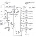
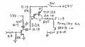
I think my drawing answers most of your requirements. R3-C1 sets the period between firings; also R3 could be a multi step switch with resistors to set different times. R1 selected to average value of R3. SW2, momentary , NO, push-button, parallels R1 & R3, approximatley halving period if held down- less if burped. SW3, clamps V on C1 to just below trip point, delaying firing untill SW is released. The big OR gate D 2-19 allows normal sequential firing or the big bang- salvo, providing 24 V supply can deliver 10 A., Could add a large cap to 24V supply- 10,000 μF, for 1 to 2 milli sec. SW 4 starts the clock, 555, and must be held for one count , U2 out 0 advances to 1. Jumping to other drawing, R20, is optionall, is to protect against short circuit damage to TIP125. Look them over, then ask your questions. Note: I have shot off many hundreds of blasting caps with in-house equipment- but that was a long-long time ago-1950s, so I might be a little rusty now.
 

nerdegutta

Joined Dec 15, 2009
2,689
I've got an idea in my head, but as said by CDRIVE, this is developing into a far more advanced project.

My idea includes:

4 SN74LS47
4 7-SEGMENT LED display
1 PIC microcontroller
3 CD4017
Switches
LED's
Transistors
Caps
Resistors
Diodes
SIL / DIL connections
4 MHz Crystal
7805 - regulator
...

As for now, this is a work in progress, in my head....
 

Thread Starter

robbar891

Joined Mar 22, 2011
15
Thanks Bernard.... If i have a 24v input from my firing system that has to hold (time wise) as long as the delay is set? How do i build in a test circuit?
 

Bernard

Joined Aug 7, 2008
5,784
You do your testing before applying + 24V. After 9 shots you turn off the, [ arming switch ], + 24Vs toggle SW. Could use a digital Ω meter to quickly check all 9 ckts., providing that meter does not apply more than about 10 mA to ckt. If interested in only checking continuity & not shorts, could add a LED monitoring test for each ckt with comparators, LEDs, & some resistors.
 
Thread starter Similar threads Forum Replies Date
C General Electronics Chat 32
Top