Facebook
 Google
 GitHub
 Linkedin
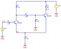
Hi, I'm trying to find the high (Vth) and low(Vtl) threshold voltages on this schmitt trigger circuit:

- The first thing I did was to asume that Q1(off) - Q2(on) so I wrote this ecuation to find Ve2 (emiter voltage of Q2):

I wrote those equations to find the emiter voltage:

Once I found the emiter voltage of Q2, then I found the condition to turn on the transistor Q1, Q1 turns on when it's base emiter junction is forward biased, so with the inequality above, I found the high threshold voltage.
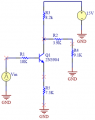
- Now I asume that Q1(On) - Q2(off)

I wrote those equations to find the emiter voltage:

As you can see the emiter voltage of Q1 depends of the imput voltage, I have tried to find the lower threshold voltage of the schmitt trigger, finding the input voltage to cut off Q1 and turn on Q2 again, but I have not succeed, , What should I do, I don't understand how to find Vtl?
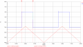
I did a simulation, Vin is the triagle wave and the blue one is the output,

Vth is about 6.32V and Vtl is about 4.77V, but I have to find Vtl analytically, and without using approximations as say that the collector and emitter currents are the same, the only approximations I have used is to fix the colector emiter saturation voltage to 0.3V and the base emiter voltage as 0.7V
- The first thing I did was to asume that Q1(off) - Q2(on) so I wrote this ecuation to find Ve2 (emiter voltage of Q2):
I wrote those equations to find the emiter voltage:
Once I found the emiter voltage of Q2, then I found the condition to turn on the transistor Q1, Q1 turns on when it's base emiter junction is forward biased, so with the inequality above, I found the high threshold voltage.
- Now I asume that Q1(On) - Q2(off)
I wrote those equations to find the emiter voltage:
As you can see the emiter voltage of Q1 depends of the imput voltage, I have tried to find the lower threshold voltage of the schmitt trigger, finding the input voltage to cut off Q1 and turn on Q2 again, but I have not succeed, , What should I do, I don't understand how to find Vtl?
I did a simulation, Vin is the triagle wave and the blue one is the output,
Vth is about 6.32V and Vtl is about 4.77V, but I have to find Vtl analytically, and without using approximations as say that the collector and emitter currents are the same, the only approximations I have used is to fix the colector emiter saturation voltage to 0.3V and the base emiter voltage as 0.7V
Attachments
-
 44.3 KB Views: 51
 -
 5.5 KB Views: 50
 -
 24.5 KB Views: 78
 -
 30.1 KB Views: 49
 -
 4.9 KB Views: 50
 -
 345.3 KB Views: 49
Last edited: