
Hi there,
I have been exploring the properties of the HV Back EMF pulses created by coils fed with a square wave input using a circuit I have constructed and which has benefited from some great advice from this forum (Battery swapper and coil driver amplifier).
In my measurements of the energy released into a battery by the Back EMF pulses, I am trying to find the resonant frequency of the coils so I can narrow my focus of the input frequency and wondered if there was a straight forward way to find this frequency practically. Bearing in mind that I am using a pulsed DC input (square wave of typically 50% duty cycle) and not a sine wave, I'm hoping there is a simple way to do it.
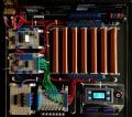
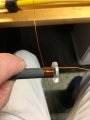
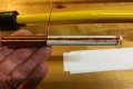
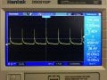
I will describe what I have in the circuit to clarify. The coils are each made up of about 500 turns of 0.71mm wire wound on ferrite cores and built up in five layers (see pics); the white paper makes it easier to see and wind them cleanly. The 7 coils each have a resistance of just under 2 Ohms and they are connected in parallel and as such have a combined resistance of about 0.5 ohms. They are fed with 12V DC from one or other of the batteries and the FET gate is driven by the square wave generator at between 20-60% duty cycle. When the FET is triggered the coils all conduct and when the FET switches off the resulting combined Back EMF pulse is directed through some diodes to one or other of the batteries. The battery swapper makes sure that the battery providing the energy for the circuit is not the one receiving the HV pulses and they switch over every 2 mins. I recognise that there is a 'flyback' diode in the FET that seeks to limit these BEMF pulses but even so the HV output is over 550V (see waveform pic - using a 20:1 potential divider) and of small pulse width producing a high voltage gradient (the effect of these high gradients is what I'm investigating).
The actual circuit pic shows my original construction with 7 FET channels which were cycled round using a CD4017 chip as I reasoned that the current through the coils in parallel would be very high (12/0.5=24A). In practice, even with all 7 in parallel, the circuit current at 200Hz is less than 0.5A so I am just using one FET channel now. At higher frequencies the current drops even further.
My query is how to find the resonant frequency of the seven coils together so I can zoom in on that input frequency range. If I knew the overall inductance and capacitance I could calculate the theoretical value but it might be easier to measure it directly in some way. I could I suppose measuring the HV pulses on the scope, as I have done, and increment the input frequency 5Hz at a time to find where the pulses are highest but that could take a long time.
Any thoughts would be appreciated.
Jules
I have been exploring the properties of the HV Back EMF pulses created by coils fed with a square wave input using a circuit I have constructed and which has benefited from some great advice from this forum (Battery swapper and coil driver amplifier).
In my measurements of the energy released into a battery by the Back EMF pulses, I am trying to find the resonant frequency of the coils so I can narrow my focus of the input frequency and wondered if there was a straight forward way to find this frequency practically. Bearing in mind that I am using a pulsed DC input (square wave of typically 50% duty cycle) and not a sine wave, I'm hoping there is a simple way to do it.
I will describe what I have in the circuit to clarify. The coils are each made up of about 500 turns of 0.71mm wire wound on ferrite cores and built up in five layers (see pics); the white paper makes it easier to see and wind them cleanly. The 7 coils each have a resistance of just under 2 Ohms and they are connected in parallel and as such have a combined resistance of about 0.5 ohms. They are fed with 12V DC from one or other of the batteries and the FET gate is driven by the square wave generator at between 20-60% duty cycle. When the FET is triggered the coils all conduct and when the FET switches off the resulting combined Back EMF pulse is directed through some diodes to one or other of the batteries. The battery swapper makes sure that the battery providing the energy for the circuit is not the one receiving the HV pulses and they switch over every 2 mins. I recognise that there is a 'flyback' diode in the FET that seeks to limit these BEMF pulses but even so the HV output is over 550V (see waveform pic - using a 20:1 potential divider) and of small pulse width producing a high voltage gradient (the effect of these high gradients is what I'm investigating).
The actual circuit pic shows my original construction with 7 FET channels which were cycled round using a CD4017 chip as I reasoned that the current through the coils in parallel would be very high (12/0.5=24A). In practice, even with all 7 in parallel, the circuit current at 200Hz is less than 0.5A so I am just using one FET channel now. At higher frequencies the current drops even further.
My query is how to find the resonant frequency of the seven coils together so I can zoom in on that input frequency range. If I knew the overall inductance and capacitance I could calculate the theoretical value but it might be easier to measure it directly in some way. I could I suppose measuring the HV pulses on the scope, as I have done, and increment the input frequency 5Hz at a time to find where the pulses are highest but that could take a long time.
Any thoughts would be appreciated.
Jules
Attachments
-
 82.1 KB Views: 28
 -
 352.6 KB Views: 24
 -
 91.5 KB Views: 21
 -
 122.4 KB Views: 19
 -
 213.4 KB Views: 23
Last edited:


