Finding a 1:1:1 signal transformer

Thread Starter

nettek

Joined Jun 4, 2018
16
Hi everyone,

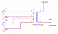
I have some device at work which serves as a testing equipment (for another device), and it has a 1:1:1 transformer. Well, in theory at least (in the schematic). In reality it has 4 pins, but never mind.
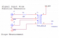
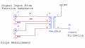
I want to make a new version of this testing equipment, something like this:

upload_2018-12-4_9-34-54.png

So as you can see, J1 is an input from an F.G and J2 goes to a scope.
I'm not really sure about why there is a transformer here, I suppose it is used to isolate the AC from the DC, or maybe add the DC signal to the AC on one of the switch positions, I don't really know.

My question is, where can I find such a transformer? I have searched Mouser and Digikey, but there are so many types and kinds of transformers, I have not idea which to choose from.

Also, bonus question. While not shown in the schematic, the testing equipment is powered from 28V, which goes to the device. Can I connect the ground from the power supply to the ground of the BNC.

Thank you!
 

Attachments

LesJones

Joined Jan 8, 2017
4,511
As well as specifying a 1:1:1 transformer you will need to specify the frquency range it has to handle. For your bonus question to be answered you need to explain how a transformer with three windings can have only 4 connections. The only way I can see is if the windings are not isolated from each other.

Les.
 

Thread Starter

nettek

Joined Jun 4, 2018
16
About the frequency, the maximum frequency from my function generator is 1KHz.

About your question, are you referring to:
Well, in theory at least (in the schematic). In reality it has 4 pins
?

If so, I can say that I can only assume it actually has 2 windings, even though it was planned to have one with 3 in the testing equipment. Since I am making a new one, I don't want to improvise but rather do things as they should be.
 

LesJones

Joined Jan 8, 2017
4,511
It is not as simple as just the maximum frequency. If a transformer is used below it's design frequency the core will saturate causing it to draw too high a magnetizing current. As it is fed from a function generator even though the base frequency is 1 Khz if the output is a square wave or sawtooth it will contain harmonics that go up to a much higher frequency. If it cannot handle these harmonic frequencies the fast edges of the waveform will be degraded. I think you may have to pay a transformer manufacturer to design one to meet your specifications.

Les.
 

ebp

Joined Feb 8, 2018
2,332
The only common 1:1:1 transformers I know of are telephone line coupling types. I believe there are also types for low-level high-quality audio.

There are lots of "control" transformers with split primaries and secondaries so you could produce 1:1:1:1 (turns ratio not exactly 1:1 primary to secondary because they are designed to deliver nominal 1:1 voltage ratio at full load so the turns ratio is designed to compensated for resistive loss). These of course are intended for AC mains frequencies.
 

Thread Starter

nettek

Joined Jun 4, 2018
16
It is not as simple as just the maximum frequency. If a transformer is used below it's design frequency the core will saturate causing it to draw too high a magnetizing current. As it is fed from a function generator even though the base frequency is 1 Khz if the output is a square wave or sawtooth it will contain harmonics that go up to a much higher frequency. If it cannot handle these harmonic frequencies the fast edges of the waveform will be degraded. I think you may have to pay a transformer manufacturer to design one to meet your specifications.

Les.
If the output from the function generator is only a sine wave, do the problems you listed still exist?

Also, something I noticed - the output I am measuring at "J2" (right now these are just + and - terminals) is about 3 times smaller than the F.G output - meaning, if I output a 1KHz 9V PK-PK signal, I see at "J2" a 1KHz 3V PK-PK signal. So, is the transformer there (could it actually be a choke?) still a 1:1:1 as I described in my schematic?
 

Alec_t

Joined Sep 17, 2013
15,112
Is there continuity between all four pins? If so you may have an auto transformer with taps at 1/3 and 2/3, which could account for the reduced scope voltage.
 

Reloadron

Joined Jan 15, 2015
7,868
As drawn your transformer could be just about anything from a re-purposed dual primary step down transformer to a custom made or special purpose transformer. Just as an example a dual primary transformer would involve pins 7&8 being tied together and pins 5&6 being tied together for maybe 120 VAC input applied or pins 5&7 tied with pins 8&6 for a 240 VAC input with the secondary being anything on pins 2&11. That would be re-purposing a common off the shelf part. The 50 Ohm resistor leads me to believe the intent was to match the impedance out of the function generator. That or it's a heck of a coincidence? :)

With SW 1 in the upper position TP1 will be whatever VCC is to VCC Common which is not shown? The rest of the circuit is doing nothing at that point for whatever the UUT (Unit Under Test) is.

This part of a test fixture was designed with a purpose in mind to do something. Knowing how it is used to do what would go a long way in solving this. A few screen shots of what is on the scope as to signals would also help. Obviously when using the test fixture there should be a written test procedure?

As drawn, making resistance measurements on pins as you labeled them J2 pins 7&6 should read a resistance. J1 pins 8&5 should read the same resistance plus about 50 Ohms. Pins 2&11 should read what could be the transformer secondary winding resistance. Again, that is with a good many assumptions on my part.

It looks like, as drawn, the objective is to impose an AC signal from the function generator on a VCC DC level and the scope output is merely to setup the function generator amplitude and frequency. SW 1 allows for either DC VCC or a VCC with superimposed AC signal.

Ron
 
Last edited:
Top