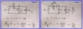
Find the impedance at resonance RLC

Thread Starter

KevinEamon

Joined Apr 9, 2017
284
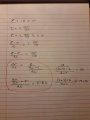
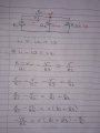
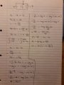
I'v never seen the differential flipped upside down like that Anhnha. This section down here were the little red arrow is pointing.

Apart from that... check out my shizzle :)

Oh 1 other thing. Some people seems to integrate 1/x = log x
Others = ln x...

Why is that? They give completely different answers so wih?
1519607445824373050965.jpg
 

anhnha

Joined Apr 19, 2012
904
First, in your derivation you have two variables Vc and V but they are same.
Vc is the voltage across the capacitor.
Also when you use the expression i = C*dv/dt, this is the relation between voltage and current through a capacitor so V should be Vc here.

You first should study the link I sent and look at the example. It is similar to the problem.
http://aries.ucsd.edu/najmabadi/CLASS/MAE140/NOTES/dynamic-2.pdf

Oh 1 other thing. Some people seems to integrate 1/x = log x
Others = ln x...

Why is that? They give completely different answers so wih?

I always use ln(x) but if you send the link where they use log(x), I think maybe in that particular example it is something like indefinite integral.
 
Oh 1 other thing. Some people seems to integrate 1/x = log x
Others = ln x...

Why is that? They give completely different answers so wih?
The integral of 1/x is always the natural logarithm. What seems odd to you is simply a matter of definition. The spelling "log" doesn't necessarily mean the common (base 10) logarithm. For example, Mathematica uses the spelling "log" to denote the natural log:

LogDef.jpg
 

MrAl

Joined Jun 17, 2014
13,756
I'v never seen the differential flipped upside down like that Anhnha. This section down here were the little red arrow is pointing.

Apart from that... check out my shizzle :)

Oh 1 other thing. Some people seems to integrate 1/x = log x
Others = ln x...

Why is that? They give completely different answers so wih?
View attachment 147009

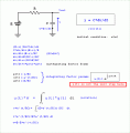
Hello again,

What do you mean by a "flipped" differential?

I was suggesting using an integrating factor for this problem. Since you got the answer now i'll show the procedure here and then soon we can move on to a new problem.
 

Attachments

Thread Starter

KevinEamon

Joined Apr 9, 2017
284
Thanks once again MrAI. I saw a few articles where the battery is labeled as E. At first I didn't like it but having read what Anhnha is saying here above, I can maybe understand the wisdom of it.
Our lecturer doesn't use that however so it's probably better I don't become overly familiar with writing it that way. Or maybe I should, a lot of the professional sites seem to follow that form.

I'd like to be able to derive the basic inductor model as well, as I just noticed something in class today. He seems to be taking everything back down to those two models.
Like for example if there were 2 resistors, he seems to be doing a themin equivalent first (at least I think that's what he's doing) defining it as R_T and then doing the simple model derivation. I think...possibly.

Anyways what else... oh sorry when I say flipped upside down - what I mean is:- in math when we done U substitution, the next thing would be dv/du rather than du/dv. I'm assuming that's what's giving the -1 value. Though I could be wrong about that as well.

I'm off to write out what you have above here MrAI - so I can understand it in my tiny brain. :)
Then I'm going to try and derive the RL circuit. Keep firing out the info or questions, I get to them. The great thing about the forum is you can always re read what everyone is saying and I often do. Thanks once again.
 

Thread Starter

KevinEamon

Joined Apr 9, 2017
284
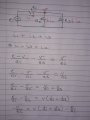
You've lost me at this point MrAI my math is reasonable. But..... wth?

Lul...

I think what I'll do for that one is just learn what I have up there... But I might adopt the E notation.

15196787010292111477494.jpg
 

MrAl

Joined Jun 17, 2014
13,756
You've lost me at this point MrAI my math is reasonable. But..... wth?

Lul...

I think what I'll do for that one is just learn what I have up there... But I might adopt the E notation.

View attachment 147079
Hi,

Not sure what you are doing here.

You have:
(E-v)/RC=dv/dt

so to get this into integrating factor form all you have to do is expand the left hand side:
E/RC-v/RC=dv/dt

and then:
E/RC=dv/dt+v/RC

and then to be very explicit to the form:
E/RC=dv/dt+v*(1/RC)

and perhaps turn everything around:
dv/dt+v*(1/RC)=E/RC

and now it is in the form that is ready for an integrating factor solution.

Make sense?
 

Thread Starter

KevinEamon

Joined Apr 9, 2017
284
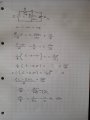
Ah ok cool. Now this makes more sense. I must have read the thing wrong. I think I'm happy enough with those capacitor derivations now. I've been learning a formulation the past few hours. 1519692594836769861726.jpg
 

Attachments

MrAl

Joined Jun 17, 2014
13,756
Ah ok cool. Now this makes more sense. I must have read the thing wrong. I think I'm happy enough with those capacitor derivations now. I've been learning a formulation the past few hours. View attachment 147090
Hello again,

Oh yes very good :)

The most important point here after reading your replies is that we have to know the relationship for each element as to the current and voltage.

The voltage is the "across" variable and the current is the "through" variable, and knowing that for any element allows us to write an expression that solves a network. Of course time enters into the picture when we have to use derivatives as with the cap and inductor.

The main three are:
E=I*R (resistor)
i=C*dv/dt (cap)
v=L*di/dt (inductor)

Sometimes we use the integral forms but you can see in each of those they have both current and voltage in some form or another. The voltage is always the across variable and the current is always the through variable.

For the next circuit, how about if we just add one resistor to what we already have?
Add R2 across the capacitor. So R1 is in series with the input voltage E, and R2 is in parallel to the cap.

Can you solve that one now?
Remember to first think in terms of current and voltage and try to write the expression for the current and voltage right near the component as that could help you see the expression you need faster.
 

Thread Starter

KevinEamon

Joined Apr 9, 2017
284
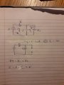
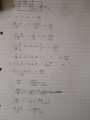
Ok but I'm back to having absolutely no idea what I'm doing.

Should I write 2 kvls and try to combine the equations?
Or maybe try and express a R total like the pic below? Then go back to the simple rc circuit?

15196994710931390335921.jpg
 

MrAl

Joined Jun 17, 2014
13,756
Ok but I'm back to having absolutely no idea what I'm doing.

Should I write 2 kvls and try to combine the equations?
Or maybe try and express a R total like the pic below? Then go back to the simple rc circuit?

View attachment 147104
Hello again,

Well digress slightly, change the cap to a third resistor R3, then try to write the equation for the output voltage without first combining the two resistors in parallel (R2 and R3 that is).

It may be worthwhile to cover some basic Nodal analysis.
 

MrAl

Joined Jun 17, 2014
13,756
Hi,

You've really said it all with i1=i2+i3, conservation of charge. Or as many people like to write, i1+i2+i3=0.
Now just replace one of those with C*dv/dt and go from there. We know for the cap i=C*dv/dt so say we make i3=C*dv/dt. We also know the voltage is v, so we know the current through R2 because we know the voltage. You know what the voltage is across R1 too right?
 

MrAl

Joined Jun 17, 2014
13,756
Ok I've been wrong twice today already so I'm going to go for the 3rd here.

Is i1+i2+i3=0?
or
is i1-i2-i3=0?
Hi,

Nothing wrong with being wrong, as long as you are willing to find out why. Once you find out why, you wont be wrong in the future.
To quote a Monk episode, "The more you know the less you dont know" ;-)

Read Kirchoffs laws.
1. The sum of currents entering a node equals the sum of currents leaving a node. i1=i2+i3.
Or stated another way, the sum of currents entering a node equals zero. i1+i2+i3=0
Note that both are true, but the direction of current for i1 (or i2 and i3) is different for the two. Dont get too hung up on that, just use either one.
2. The sum of voltage drops around a closed circuit equals zero. v1+v2+v3=0.

If we had a 2v source and R1=1 and R2=2 and R3=2, we have:
iR1=iR2+iR3

which in terms of voltages is:
(E-v)/R1=v/R2+v/R3

Now one of those in the real circuit is a capacitor, and we said R3 would be replaced, so just replace that with the definition of current for a capacitor. See what that leads to as that is one more step toward the solution.
 

Thread Starter

KevinEamon

Joined Apr 9, 2017
284
Ahh indeed... ok sorry for the delay was v busy yesterday. How' this looking so far? I can possibly see a few missed things but I think some of its right. Ive used the same values for R so I can understand this without complications

15199164892002054501799.jpg
 

MrAl

Joined Jun 17, 2014
13,756
Hello again,

I think you are getting better at this now :)

We should concentrate mostly on your first two equations, which are correct BTW. The only difference i would add is that if we have two different resistors then we need R1 and R2 so we cant make them both R.

The attachment shows the two resistors, and you can see i made some other small changes i'll list here.
1. The current arrows are always INSIDE the wire itself where the current is flowing.
2. The voltage arrows are always OUTSIDE the circuit element, and the tip of the arrow is adjacent to the assumed positive terminal and the tail is adjacent to the assumed negative terminal of the element.
3. If there are two resistors then they should be labeled R1 and R2 unless you really want them both to have the same value resistance fo any circuit you will encounter like this. Using R1 and R2 is more general and so allows the solution to represent a wider class of circuits. It is also better for practice purposes. It also makes discussion of the circuit easier because then we know what resistor we are talking about.
4. I labeled the voltage across R1 "vR1" so this is not "v*R1". I just did that to show how the voltage arrow would look for that resistor. We could have also labeled it "E-v" for example, but the arrow would be the same.
5. Clarity is important. If the work is blurry or hard to read it will make it very hard for people to follow your work. That means the text should be clear or else someone will have to keep asking you questions about the meanings. Certain characters are easily confused if not drawn or typed carefully, such as "i" and "1" and "o" and "0" and the like. For some fonts the lower case "L" looks very much like a number "1" so that is something to watch out for too.

Of course some of these things seem very picky and it very well may be so for a simple circuit like this, but when you get to more complicated circuits you will appreciate this level of detail a lot more.

After all is said and done though, i think you did pretty well with this circuit and as i said for you i think the most important part was the first two equations and you got that right so i am happy about that :)

The solution, once you get the equation such as your second equation, will always be algebraic or require a little calculus as you know. This means we switch from "circuit analysis" to "pure mathematics". For the circuit part you just have to know how to write the equations, and for teh pure math part you have to know the math. If you know algebra and differential equations then you should not have a problem with the math part.

I did not check your math yet, but i will do that next. I just wanted to quickly make a few comments about the first two equations.

Two little questions:
1. Did you study Laplace Transforms yet? Dont worry about it too much if you didnt i just wanted to know.
2. Are you ready for another circuit ? :)
 

Attachments

Thread Starter

KevinEamon

Joined Apr 9, 2017
284
Pretty cool and you're right of course but I just want to ask you a few things, if that' ok?
Currents I get, that' good. This thing people do with voltage pointing back to the source, it doesn't seem intuitive to me, using the water analorgy, the potential difference is "tipped" up a the source end. So I don't get that.
Once again just to state you'e right I'm the one asking, but why did you remove the voltage arrow across the capacitor?

Regarding calculus. I got 90% in my last exam... which is quite an achievement for me compared to where I was last year...
Give me a few X Y equations and I'm all good.
I just dont really understand what is happening when applied to real world things.
I understand now why the voltage disappears. It's a number right? So it just goes to 0.
Nothing seems to happen to the R/L for example in post 48 step 8... only that the dt goes to t...
And again with the dt/RC in post 50.
1/x I know always goes to ln l x l. So I kind of understand what's happening there.

In post 61 I don't like the way I've introduced that constant c = log v
I much prefer the way I did it going back to post 48 using the limits. So I'd like to rewrite that one, if I figure it out.

In the mean time I'm going to have a go at your circuit using R1 R2. In lecturers here now, then work . So I'll reread all what you'e said again later, when I can sit down with a bit of paper and pen... my happy times... everything else is a distraction to me these days... I'm going to make a meme for work.... - "rather be doing calculus" :)

Oh I've done laplace but again it was a math teacher, lecturing us. We'd probably be much better with an engineer teaching that module...Though I did love my lil math teacher tbh.
 
Top