You seem to mix all thing together!
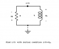
Let's start with the circuit from MrAl image:
KVL law states that for a closed loop series path the algebraic sum of all the voltages around any closed loop in a circuit is equal to zero.
So let's apply KVL to the loop created by resistor and inductor above.
VR + VL = 0. (1)
With passive sign convention and current as above, let's see how VR and VL are related by the current i(t).
With ohm's law: VR = i(t)*R
For inductor, the relation between its voltage and current is VL = L*di(t)/dt
Substitute VR and VL into (1) above:
R*i(t) + L*di(t)/dt =0
Now we have to solve this equation. There are several methods to deal with this. However, let's make sure that you understand the derivation above first.
What Anhnha is showing you looks good so you can follow that. What else though is that for a starting circuit this may be a little too atypical so dont get too alarmed if it seems difficult or impossible. We'll move to a more typical circuit next where ground has more significance too and that's what a lot of people prefer.
So if i tell you anything with this post, let it be not to get too alarmed if you have a lot of difficulty solving this one, but you may learn from it just the same. Even if you dont learn from it though dont worry too much
Oh yeah one small thing though, if the problem asks for a solution to i(t) then that should be somewhere in the solution.
K you're probably gonna beat me over the head for this nonsense but I've next to no skill in circuit calculus. Seems to be different from normal calculus. Though I know that' probably not the case and I just don't understand it. I'm also aware I didn't introduce the integrating factor. Do you just assume it, or is there a proper way to bring it in?
Well, perhaps we should go through this one and you can see if you understand all the steps. Once you see some of these being solved you will pick up on it. We do have two distinctly different areas of study here though, one is writing circuit equations and the other is solving differential equations. Each requires a different technique. The main idea here is to write the circuit equations but the DE is only first order so it is not that hard to solve.
In the following...
Int means integrate
Io means the initial current I sub 0 which we wrote I0 previously but Io looks better.
Sum of voltages around a closed circuit equals zero:
VL+VR=0
Replace with known quantities:
di/dt*L+i*R=0
Separate variables (di goes with i, dt goes with t):
di/dt*L=-i*R
di*L=-i*R*dt
L*(di/i)=-R*dt
Divide by L:
di/i=-(R/L)*dt
Now that the vars are separated, we can integrate. We know the current goes from Io to i(t) and time goes from 0 to t.
Int(1/i)di [from Io to i(t)]=-Int(R/L)dt [from 0 to t]
The result of integrating both sides by their respective vars:
ln(i(t))-ln(Io)=-R/L*t
Take both sides to a power of 'e':
e^ln(i(t))/e^(ln(Io))=e^(-R/L*t)
Simplify:
i(t)/Io=e^(-R/L*t)
Get i(t) (the solution we need) on one side:
i(t)=Io*e^(-t*R/L)
All steps with no explanations:
VL+VR=0
di/dt*L+i*R=0
di/dt*L=-i*R
di*L=-i*R*dt
L*(di/i)=-R*dt
di/i=-(R/L)*dt
Int(1/i)di [from Io to i(t)]=-Int(R/L)dt [from 0 to t]
ln(i(t))-ln(Io)=-R/L*t
e^ln(i(t))/e^(ln(Io))=e^(-R/L*t)
i(t)/Io=e^(-R/L*t)
i(t)=Io*e^(-t*R/L)
See if you can follow that, and if anything seems questionable just mention that and we can talk about it.
After this we can move to a more typical circuit and that should get us going faster.
You'e a star MrAI!
I'm in lecturers most of today, soon as I get some free time, consuming this till I can do it without notes, is top of my agenda!
Thank you v much.
Excellent for the first time I think I actually understand this thing..Now for my next amazing feat. Does anybody want to know how much gold is in their crown?
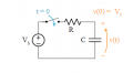
Actually that looks right i'll check it, but the next circuit is as anhnha showed but with no initial voltage in the cap. We can add that later.
You can use the integrating factor for this one.
Something much more important MrAI. I understand the methodology!!!
...
^ these 3 dots represent the massive rant about my lecturer, which I just deleted.
Anywho office politics aside... yes I do. I think, with maybe one small issue. If you see post 48. Step 8. The right hand side of the equation. Integral -(R/L). In my normal calculus a constant R would have been ( R^2 ) /2. We're as 1/L would have been = ln L.
But as I say the methodology was much more helpful to me. Now I understand what we're doing and why we're doing it.
Thank you V much.
I'm going to have a crack at this circuit in post 51 later... I'm currently speaking to you from the land of the Sandman zzzzzzzzzz
KevinEamon, for some more practice return to the beginning of this thread. The impedance of the resonant RLC circuit was found using as the definition of resonance that the impedance has zero phase angle. This is the same as saying that the imaginary part of the impedance is zero.
Let the definition of resonance be that (ω L) = 1/(ω C). Calculate the impedance of the circuit using that definition of resonance.
Something much more important MrAI. I understand the methodology!!!
...
^ these 3 dots represent the massive rant about my lecturer, which I just deleted.
Anywho office politics aside... yes I do. I think, with maybe one small issue. If you see post 48. Step 8. The right hand side of the equation. Integral -(R/L). In my normal calculus a constant R would have been ( R^2 ) /2. We're as 1/L would have been = ln L.
But as I say the methodology was much more helpful to me. Now I understand what we're doing and why we're doing it.
Thank you V much.
I'm going to have a crack at this circuit in post 51 later... I'm currently speaking to you from the land of the Sandman zzzzzzzzzz
That's good. I was thinking maybe you should try writing the equation(s) first, then we could concentrate on solving them later.
You would get a lot of practice writing the DE equation(s) that way, and that is one half of the battle.
I think you have the right idea but you have to use the right relationship for each component according to what it is. Each component has a specific relationship for current and voltage and that is what is at the heart of all of this. In other words, once you know the current voltage relationship for the various components you can use that to solve the circuit, along with some simple circuit laws. These begining relationships are most important though.
For example, we have Ohm's Law for a resistor element, stated in one form we have:
V=R*I
but we have a sort of Ohm's Law for the capacitor (and inductor) too, although time is also involved. For the cap we have:
i=C*dv/dt
and there we see we have three things involved:
current, voltage, and time,
and we have to get each one in the right place.
We can change the form a little:
dv/dt=i/C
but we can not change the variables v, i, or t.
What you have in your first equation is C*di/dt and that is totally incorrect because that's not how a cap works.
It is i=C*dv/dt, and for the inductor it is v=L*di/dt.
Note one uses dv/dt and one uses di/dt and you can not swap them.
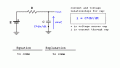
In post #52 i tried to state this as clear as possible, and showed WHERE the voltage and current was and how it related to the derivative of the voltage across the cap.
So we need to know WHAT the relationship is (just like in Ohm's Law for resistors) and we also need to know WHERE the current and voltage is for that relationship in the circuit. I think you have the WHERE correct, but you need to work on the WHAT. What the relationship is for each element, and dont vary from that.
I'll state the differential forms again:
i=C*dv/dt
v=L*di/dt
This is just like using Ohm's Law, except instead of:
i=V/R
we use:
i=C*dv/dt
Take a look at post #52 and see if that helps, then try to write the equations again, especially the first one.
Ok sorry I though you could simply just reverse the variable and the differential would give you the desired voltage.
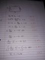
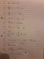
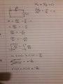
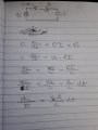
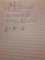
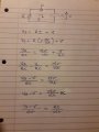
I was reading through your notes here and a few other things. This is what I've come up with so far. But now I feel I may be departing from your method again MrAI, which I quite like. I dont want to do that...So I'll pop this up and see. How does this look?
You got the equation correct but it seems that you don't know how to solve a differential equation that is different from the one given by MrAl.
Do you know how to solve first order linear differential equation? You may want to study it first, it is just math now. http://aries.ucsd.edu/najmabadi/CLASS/MAE140/NOTES/dynamic-2.pdf

 Facebook
 Google
 GitHub
 Linkedin