Filtering signal from transducer.

Thread Starter

Rokeeeez

Joined Feb 8, 2018
19
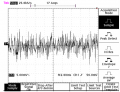
Hello dear colleagues, i have some questions for you about signal filtering. I want to project daq for my pressure transducer. Firstly, I have a signal from transducer (voltage about 30-60mV), then i design differential amplifier with gain of 20, and the output voltages transducer now are 500mV-1,1V, but when get a signal in osciloscope, there are a lot of noise. So, the question is, what filter is best to use for this type of signal (pressure transducer), also I want to know when it is better to filter signal? Before amplification or after differential amplifier?. I read some information on the internet and I understood, that one of the option for this situation is passive low pass (RC) filter, but I didnt know what value of cutoff frequency should be, and also low pass filter will attenuate my useful signal. So, guys, I would be thankful if you suggest some solutions.

Transducer datasheet: http://technel.com/Files/AB-HP.pdf

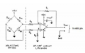
Differential amp schematics is attached, i use LM324, instead LMC6484.
 

Attachments

Thread Starter

Rokeeeez

Joined Feb 8, 2018
19
I didn't know exactly maximum frequency change of pressure sensor, I know, that output of pressure sensor before amplification will be in range about 30-60mV.
 

dendad

Joined Feb 20, 2016
4,476
What are you measuring the pressure off? If it is something like a tank of water, the pressure will not change rapidly so a long time constant filter can be used. So it will help if you tell us what you are trying to measure.
 

Thread Starter

Rokeeeez

Joined Feb 8, 2018
19
What are you measuring the pressure off? If it is something like a tank of water, the pressure will not change rapidly so a long time constant filter can be used. So it will help if you tell us what you are trying to measure.
I measure a pressure from blood pressure pump. I manualy push the pump to 400mmHg and then i release the air with the same intervals of 20mmHg. From 400 mmHg to 0 mmHg (400-380-360-340-...-0). It's experiment now, because i want to get clear relatiionship between presure and voltage. Later i use real blood pressure monitor.
 

dendad

Joined Feb 20, 2016
4,476
How clean is your 5V supply? Are you using a linear or switch mode supply?
One thing that may help is to decouple the supply to the bridge and even have a 3.3V low drop out linear regulator for it running off the amp 5V.
The bridge output will be less on 3.3V but if the supply is cleaner, so will the noise. A lot will depend on your construction. A breadboard is probably not the bst unless a lot of care is taken for short wires. And you will need more than just the single 100nF cap I suspect.
What is the noise? It is mains hum or just random?
Shielding the circuit can be a good idea too.
Can you post a picture of your circuit setup?
 

OBW0549

Joined Mar 2, 2015
3,566
So, the question is, what filter is best to use for this type of signal (pressure transducer), also I want to know when it is better to filter signal? Before amplification or after differential amplifier?
It's usually best to filter before the amplifier rather than after.

As for how to implement a noise filter, see page 20 of this data sheet, and the diagram in Figure 49. A filter of that type will handle both differential-mode and common-mode noise. The associated text explains the relation between the resistor and capacitor values and the resulting filter cutoff frequency.
 

Thread Starter

Rokeeeez

Joined Feb 8, 2018
19
How clean is your 5V supply? Are you using a linear or switch mode supply?
One thing that may help is to decouple the supply to the bridge and even have a 3.3V low drop out linear regulator for it running off the amp 5V.
The bridge output will be less on 3.3V but if the supply is cleaner, so will the noise. A lot will depend on your construction. A breadboard is probably not the bst unless a lot of care is taken for short wires. And you will need more than just the single 100nF cap I suspect.
What is the noise? It is mains hum or just random?
Shielding the circuit can be a good idea too.
Can you post a picture of your circuit setup?
Power supply for my pressure transducer is from usb, 5V, for amplifier is 5V from arduino, and all circuit is designed on breadboard.
I attach a picture from the internet with noise, so in osciloscope i saw something similar to this, i think this is white noise.
 

Attachments

Thread Starter

Rokeeeez

Joined Feb 8, 2018
19
It's usually best to filter before the amplifier rather than after.

As for how to implement a noise filter, see page 20 of this data sheet, and the diagram in Figure 49. A filter of that type will handle both differential-mode and common-mode noise. The associated text explains the relation between the resistor and capacitor values and the resulting filter cutoff frequency.
I tried to project filter for both inputs of my amplifier. (Before amplification) - R is 10kohms, and C is 10nF, but then after amplification, output voltages decreases. (Without filter voltages are 500mV-1.1V, with filter are only 60-100mV).
 

dendad

Joined Feb 20, 2016
4,476
It will probably be better to run the bridge from the Arduino supply, not the USB. Just for a test, try the Arduino 3.3V for the bridge.
Depending of how you have it all hooked up, running 2 different supplies can in itself introduce noise.
Run the bridge from the Arduino 3.3v, (or the Arduino 5V), via a 100R resistor, and add a 10uF tantalum cap across the bridge.
 

OBW0549

Joined Mar 2, 2015
3,566
I tried to project filter for both inputs of my amplifier. (Before amplification) - R is 10kohms, and C is 10nF, but then after amplification, output voltages decreases. (Without filter voltages are 500mV-1.1V, with filter are only 60-100mV).
Then something is wrong: bad connection, wrong component value, something. That filter design works.
 

ebp

Joined Feb 8, 2018
2,332
The excitation for the bridge transducer needs to be a very clean very precisely regulated voltage that should come from a voltage reference, not some crude supply like USB 5V or Arduino 5V. Any noise on the excitation of the transducer will show up on the output. I strongly suspect that this is where almost all of the noise is coming from. That is an expensive transducer. Spend $10 and get it a precision voltage reference.

The input filter in the datasheet OBW linked to requires great care to prevent degrading the common mode rejection of the amplifier. The resistors should be 0.1% tolerance, the small capacitors 1% tolerance and types with low dielectric absorption (C0G ceramic are OK, no other ceramic is any good; polypropylene film is good, most other plastic film types are bad). The large capacitor tolerance doesn't matter, but it should also be PP film or C0G ceramic.

The signal connections from the bridge to the amp should be twisted together and the excitation and ground should be twisted together.
 

ebp

Joined Feb 8, 2018
2,332
Determine how much excitation current is required for the bridge. If you are lucky, it will be low enough that you can use a reference without the need to buffer it. Buffering is not very difficult, but it does add a few more parts.

I suggest a 4.096 V (sometimes called 4.1 volt) series reference. These are quite common and there are lots of choices. You need one that will work with an input voltage down to about 4.5 V input. Better (more expensive) references will have better initial voltage accuracy and lower drift with time and temperature. Add an LC filter ahead of the reference. I recommend using a resistance of a few ohms (probably in the range of 2-10 ohms) in series with the inductor to "spoil the Q" of the filter so it does not peak very sharply at resonance, which can sometimes cause problems when the input is noisy. Read the datasheet for the reference very carefully and follow advice on input and output capacitors.

You will need to increase the gain of the amplifier to compensate for the lower excitation voltage for the bridge.

The circuit you have now reduces the performance of an expensive transducer to the level of one that should cost $2.

Remember that there is ONE POINT in a circuit that can be considered zero volts. This must be considered very carefully with plug-in breadboads and strings of off-the-shelf circuit boards strung across the bench.
 

mlv

Joined Nov 6, 2017
17
The circuit diagram you posted shows that the signal is sent to an ADC. I expect the requirements for analog filtering to depend on your ADC, whether it has anti-aliasing filtering at its inputs or not and what its sampling frequency is. Assuming that the ADC sample rate is oversampled, you might want to be generous with analog filtering and then do digital filtering of the ADC output to refine the signal. This gives a lot of desirable benefits: control, performance, predictability, device yield, calibration, etc compared to a high-order analog filter.

You could also investigate the signal in the digital domain for spectral content, before-and-after plots of time-domain, and so on to determine what filters to use in a given scenario.

Of course, all of this presumes that you have post-processing capacity or digital HW datapath for doing digital filtering.
 

ebp

Joined Feb 8, 2018
2,332
I forgot to mention previously:
I generally consider the bandwidth of this sort of thing to be "zero." Of course it isn't really zero, but it is very low. If you were using an intra-arterial pressure transducer it would be a different matter.
 
Top