Filtering HV pulses

Thread Starter

JulesP

Joined Dec 7, 2018
458
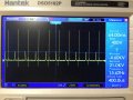
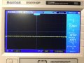
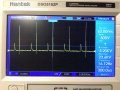
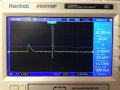
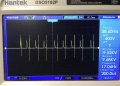
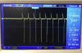
Here are a couple of screen shots using just two of the 20kV diodes in series I.e. with no diodes between HV and ground as they haven’t arrived yet.

One shows the situation without the diodes and the other with (approx +- 9kV).

The first thing one can see is that there is now of sharp spike of +9.68kV as well as a smaller one of -9.52kV alongside the +6kV present without the diodes. So using the diodes has created an additional + spike and reduced, but not eliminated, the negative one.

Any thoughts on what’s happening there?
 

Attachments

Thread Starter

JulesP

Joined Dec 7, 2018
458
So the diodes might be filtering the large negative spikes out but then adding their own + and - spikes to the music
 

Deleted member 115935

Joined Dec 31, 1969
0
Just a thought,
these spikes you seeing on your scope with the 1000:1 probe on it,

These things are very short, and have a fair amount of current in them
Im wondering, are they picked up without the probe connected to anything, just near by
or even with no probe, just from the scopes power lines,
 

Thread Starter

JulesP

Joined Dec 7, 2018
458
I will check in the next day or so and report back. As far as I’m aware the spikes without the diodes are what’s coming through via the 1000:1 divider.
 

Thread Starter

JulesP

Joined Dec 7, 2018
458
Ok so here’s what I get with and without the scope leads connected to the 1000:1 probe.

If some inductive pickup was happening then this would show with the leads disconnected and everything else the same.

This indicates that the spikes are all coming from the coil secondary and diode arrangement and assuming the potential divider probe is not adding anything.

When I get two more of these HV diodes then I will put them between the HV line and ground in reverse bias and remove the remaining negative spikes. If I have extra very short duration positive ones then that should not be a problem for the plasmolysis cell.
 

Attachments

MisterBill2

Joined Jan 23, 2018
27,528
I suggest connecting a diode across the primary of the ignition coil, (pointing up as the circuit is drawn) This will reduce the spike quite a bit. Thediode will need to be rated at least 200, volts, but a 600 volt diode will give a better safety margin. The problem is that both rise and fall of the primary current are quite fasy, and so both voltage spikes are high. The diode, possibly with a series resistor added,will reduce the spike from the collapsing magnetic field quite a bit.
 
Last edited:

shortbus

Joined Sep 30, 2009
10,050
I have my doubts the spikes will ever get resolved, by any means if this is one of the old round ignition coils. The spikes are one of the reasons they changed to an E core ignition coil when they went to electronic HEI type ignition. This is not something I made up but is from an engineer that worked on the HEI development when I was still working at Delphi.
 

Thread Starter

JulesP

Joined Dec 7, 2018
458
I suggest connecting a diode across the primary of the ignition coil, (pointing up as the circuit is drawn) This will reduce the spike quite a bit. Thediode will need to be rated at least 200, volts, but a 600 volt diode will give a better safety margin. The problem is that both rise and fall of the primary current are quite fasy, and so both voltage spikes are high. The diode, possibly with a series resistor added,will reduce the spike from the collapsing magnetic field quite a bit.
I can see the logic of a diode here and orientate it according to which pulse polarity I’m trying to remove. From memory the IN5407 can manage 1000V reverse voltage.

A related question is regarding the magnitude of the main secondary voltage spikes. The coil is specified to produce 10-15kV but I’m only getting 6kV so I’m assuming that voltage is a function of the rate of change of primary flux which will be a function of the shut off time of the FET. Is there a simple way to reduce the FET shut off time to increase the main secondary voltage spike?

When I get the extra HV diodes I should be able to remove the unwanted polarity spikes whatever their cause.
 

DickCappels

Joined Aug 21, 2008
10,661
Use a gate driver to speed up the MOSFET.

Note: The 1N5408 is the one rated to 1000V. The reverse recovery time was not available on the datasheet I found.
 

BobaMosfet

Joined Jul 1, 2009
2,211
I have finished the construction of an HV supply (that was in part the subject of another thread) and it is producing hefty sparks (and where a short video of it working can be seen at: https://www.dropbox.com/s/n2z0de5k1pu6fk4/Coil HV.MOV?dl=0 )

My query is regarding the resulting voltages that I measure with a 1000:1 voltage divider probe (see pics). By adjusting the primary voltage (with the MJE3055) I get a range of secondary voltages from +3.8kV to +6kV and -16.4kV to -33.2kV as shown in the images. This negative voltage, with its shorter duration, I presume is some form of BackEMF that I would like to remove from the supply to the plates of my HV plasmolysis cell so there is only one polarity hitting the plates.

Is there an easy way to block these? I imagine most diodes won't take the hit but there might be another way. Alternatively, at some stage, I might need to remove the positive peaks and just keep the higher value negative ones.

Thanks
@JulesP You don't say (or I missed it) where your test point is. Looks like you're connected to one side of the MOSFET, but...? Also, can you widen your scale so we can see the decay of the larger negative pulse, this will show it's discharge time better.
 

Thread Starter

JulesP

Joined Dec 7, 2018
458
@JulesP You don't say (or I missed it) where your test point is. Looks like you're connected to one side of the MOSFET, but...? Also, can you widen your scale so we can see the decay of the larger negative pulse, this will show it's discharge time better.
My test point for the HV is the upper of the ‘Spark Gap’ points on the circuit diagram that then connects to the 1000:1 probe (see attached). The only test point connected to the FET is the Gate to detect the frequency and shown as TP1 on the circuit.

When I’m back next week I will expand the time axis to try and show the decay of the negative pulses.

B5ADE905-7D54-4D25-B106-FA59BFE4DCE5.jpeg
 

Thread Starter

JulesP

Joined Dec 7, 2018
458
@JulesPAlso, can you widen your scale so we can see the decay of the larger negative pulse, this will show it's discharge time better.
Here are a couple of traces showing the ‘normal’ one and another zoomed in with the time axis expanded.
Without accurate measurement I would say the sharper spikes have a FWHM of about 900us-1ms.
 

Attachments

MisterBill2

Joined Jan 23, 2018
27,528
OK, now the vast majority of the energy is in the positive direction. So now a set of diodes can feed a capacitor and you will have a positive DC voltage. If you want a negative DC voltage you will need to exchange the connections to the coil primary terminals.
 

Thread Starter

JulesP

Joined Dec 7, 2018
458
Well if I short to ground the negative part of the spikes using some more HV diodes then I should still have the +6 and +25kV spikes, albeit of different decay times and energy content, to contribute towards plasma formation. I’m hoping there is enough energy in the pulses to achieve that. Anyway that’s what experimentation is all about.
 

MisterBill2

Joined Jan 23, 2018
27,528
Well if I short to ground the negative part of the spikes using some more HV diodes then I should still have the +6 and +25kV spikes, albeit of different decay times and energy content, to contribute towards plasma formation. I’m hoping there is enough energy in the pulses to achieve that. Anyway that’s what experimentation is all about.
Itwill make more sense to just block the negative spike with diodes in series. And you will still need a filter capacitor. Diodes do not filter at all, they block or pass.
 

Thread Starter

JulesP

Joined Dec 7, 2018
458
Itwill make more sense to just block the negative spike with diodes in series. And you will still need a filter capacitor. Diodes do not filter at all, they block or pass.
That’s what I already have following earlier suggestions but the inclusion of HV stacking diodes seems to have introduced more negative spikes. See post #21.
 
Top