 Facebook
 Google
 GitHub
 Linkedin
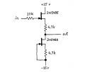
In first image there has to be dc path to ground at input yeah?
"in" is from function generator
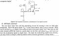
In 2nd image, from the 4th to last line: from "then tune an AM"...Please can someone explain from that point
Don't understand
Thanks
// WBahn : "As this is homework, show your attempt"
"in" is from function generator
In 2nd image, from the 4th to last line: from "then tune an AM"...Please can someone explain from that point
Don't understand
Thanks
// WBahn : "As this is homework, show your attempt"
Attachments
-
 33.7 KB Views: 20
 -
 502.4 KB Views: 22
Last edited:


