
Hello,
I had a few specific questions as well as hoping to get overall feedback and advice. I am building an off-road capable camper and for my interior I wanted to add some red map light and under seat lighting to allow visibility in the cabin that preserves night vision. My general objectives are as follows:
1. Have an Arduino generate a PWM signal to feed two LED Drivers (Two Channels) to light the LEDs
2. Use the existing car dimmer circuit (a 12v PWM) as an input to the arduino such that when I dim my cabin lights, these new lights will also dim to an extent.
3. Use the Arduino to record rapid succession of turning these lights on and off such that within a short amount of time it will cycle through (Floor Lights Only, Floor Light - Map Light on Low, Floor Lights - Map Lights on High)
4. Given that I will make a PCB board for this project, make a few extra and sell to fellow enthusiast on a forum I frequent to recover some of the cost and help those guys achieve a similar effect.
For reference, here are the lights I will be driving:
9.5 Feet of LED red light strips (forum wont let me post the link) but about 22w at 12v
and two of these (Forum wont let me post the link) 2 pods containing 3 3w cree red lights
Also for handy reference here is the LED Driver spec sheet:
https://www.mouser.com/ds/2/256/MAX16819-MAX16820-84188.pdf
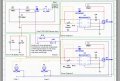
I have attached a diagram of the circuit I made for this purpose from Multisim.
My specific questions are:
1. I know that my battery voltage will be 13-16 volts depending on how it is charging at the moment, when I simulated this, I was under the impression that the bucking of the LED driver would clamp this down to 12 volts steady, and at constant amperage. This is not what I observed in multisim
A. Does this matter, are my leds going to look great and last a long time?
B. If not, how do I fix this
2. The Rsense resistor used to regulate everything is given both in the spec sheet, and the in the excel worksheet linked to in the spec sheet (the calculator). Those two sources don't agree, in the spreadsheet its telling me in a range of 3-6 amps of load, I will need a resistor between .04 to .20 ohms, tiny! even in the formula I calculate between 1 and 5 ohms.
A. am I way off, did I do something wrong?
B. how sensitive is all of this, as I want to put some pots on the final product so that other people that are using a very similiar setup (but maybe a little variance) can still use this solution.
3. I was going to simply read the pwm signal from my cars dimmer after voltage dividing it and reading it on the analog pin, any issue with doing this?
4. That dimmer connects to a an expensive 1200 dollar part on my truck, I have factored putting a .5amp fuse as well as a diode, is that enough protection to make sure my goofing around doesn't break something expensive?
5. Any and all general feedback, tips, or life lessons welcomed!
I had a few specific questions as well as hoping to get overall feedback and advice. I am building an off-road capable camper and for my interior I wanted to add some red map light and under seat lighting to allow visibility in the cabin that preserves night vision. My general objectives are as follows:
1. Have an Arduino generate a PWM signal to feed two LED Drivers (Two Channels) to light the LEDs
2. Use the existing car dimmer circuit (a 12v PWM) as an input to the arduino such that when I dim my cabin lights, these new lights will also dim to an extent.
3. Use the Arduino to record rapid succession of turning these lights on and off such that within a short amount of time it will cycle through (Floor Lights Only, Floor Light - Map Light on Low, Floor Lights - Map Lights on High)
4. Given that I will make a PCB board for this project, make a few extra and sell to fellow enthusiast on a forum I frequent to recover some of the cost and help those guys achieve a similar effect.
For reference, here are the lights I will be driving:
9.5 Feet of LED red light strips (forum wont let me post the link) but about 22w at 12v
and two of these (Forum wont let me post the link) 2 pods containing 3 3w cree red lights
Also for handy reference here is the LED Driver spec sheet:
https://www.mouser.com/ds/2/256/MAX16819-MAX16820-84188.pdf
I have attached a diagram of the circuit I made for this purpose from Multisim.
My specific questions are:
1. I know that my battery voltage will be 13-16 volts depending on how it is charging at the moment, when I simulated this, I was under the impression that the bucking of the LED driver would clamp this down to 12 volts steady, and at constant amperage. This is not what I observed in multisim
A. Does this matter, are my leds going to look great and last a long time?
B. If not, how do I fix this
2. The Rsense resistor used to regulate everything is given both in the spec sheet, and the in the excel worksheet linked to in the spec sheet (the calculator). Those two sources don't agree, in the spreadsheet its telling me in a range of 3-6 amps of load, I will need a resistor between .04 to .20 ohms, tiny! even in the formula I calculate between 1 and 5 ohms.
A. am I way off, did I do something wrong?
B. how sensitive is all of this, as I want to put some pots on the final product so that other people that are using a very similiar setup (but maybe a little variance) can still use this solution.
3. I was going to simply read the pwm signal from my cars dimmer after voltage dividing it and reading it on the analog pin, any issue with doing this?
4. That dimmer connects to a an expensive 1200 dollar part on my truck, I have factored putting a .5amp fuse as well as a diode, is that enough protection to make sure my goofing around doesn't break something expensive?
5. Any and all general feedback, tips, or life lessons welcomed!
Attachments
-
 315.7 KB Views: 8


