Facebook
 Google
 GitHub
 Linkedin
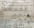
I'm looking to build a circuit monitor for use as a fault finder to see what switch drops first in the series before the entire line shuts down.
Explanation I have an escalator that keeps shutting down randomly and the safety string resets and goes back to ready to run mode.
I need to hook up a box that will monitor 8-12 points on the safety string terminal to see which switch is getting tripped first. But each terminal getting monitored can not jump to the next one basically jumping out my safety string. I hope this makes sense. I saw the plc guys talk about a first out annunciator but plc's are out of the question.
voltage is 120 ac
thanks
Andy
Last edited: