Fairy Light Project

Thread Starter

KT Depot

Joined Jan 15, 2025
9
I have tried two different fairy lights set up. First one involved multiple 24-inch strings. The second one involved 100-ft string cut down to 36 inches. In both, I had a main line that feeds the individual runs. The end result to power the light using an AC adapter.

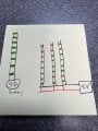
Setup #1 - the 24-inch light string is powered by two 3v lithium (CR2032) for a total of 6v. I cut the string at the battery and connect it to the main line. I repeat this for each bottle. See "partially finished". They are wired as shown in "wiring 1" - ignore the 5v, it should say 6v, just wrote it incorrectly.

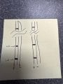
Setup #2 - the light string is 100-feet and powered by a 6v adapter. From the manufacturer, it is wired as shown on the left side of "wiring 2"; there are three wires. Left is fed positive. Right is fed negative. Middle and right are soldered at the far end. I cut the string down to 36 inches. When connecting to the main line, I use the left and middle, ignoring the right - as shown on the right side of "wiring 2".

In the second configuration, I am reducing effective length especially on the negative side from 200 feet to 3 feet. But in the first configuration, I am actually extending the overall length.

In both set up, the LED will start to burn out after several hours to several days.

What is wrong? What do I need to change?
 

Attachments

wayneh

Joined Sep 9, 2010
18,100
I suspect the voltage being seen at each LED was lower than the nominal voltage in the original configurations. You should measure. Your modifications are exposing the LEDs to higher voltage and current, reducing life.
 

Ya’akov

Joined Jan 27, 2019
10,233
Welcone to AAC.

Your problem is that LEDs care about current—not voltage. The voltages used to power the various strips account for the resistance in the circuit. This will be influenced by the length of the wires, any current limiting resistors added by the manufacturer, and, in the case of the coin cells, their ESR (Equivalent Series Resistance).

According to Ohm’s Law, which describes the behavior of most electrical circuits using direct current:
\[ \mathsf{I = \frac{V}{R}} \\ \ where: \\ \begin{align} \text{I = current in Amps (A);} \\ \text{V = voltage in Volts (V), and;} \\ \text{ R = resistance in Ohms (}\Omega\text{)} \end{align} \]
LEDs are rated for their light output at certain currents, the datasheet of the LED will tell you what that is. It is common to drive an LED at 20mA. So, if you have 5 LEDs, at 20mA each, you would drive them at 100mA to see the rated light output.

You can use less current and they will be dimmer, or more and they will be brigher. you can’t hurt an LED by underdriving it, but overdriving it can shorten its life—even to producing one bright flash and then letting out the magic smoke that makes all components work.

The reason for this is heat. Dissipating current means heating up, and heat kills LEDs over time. An underdriven LED can lasts many times longer than its rating, overdriving has the opposite effect. You LEDs are literally ”burning out“. What you need is a constant current power supply designed to power LEDs. This will vary the voltage to match the circuit’s resistance resulting in the desired current.

Such supplies are readily available online.
 

ElectricSpidey

Joined Dec 2, 2017
3,326
1. Do not use a constant current supply with parallel LED strings, as suggested.

2. Do the strings have a resistor on each LED?

The possibility on the first strings powered by the battery: There are no resistors used on the string and the Mfg. relied on battery resistance and the adapter is overpowering the string.

Second string: The Mfg. is relying on a voltage drop on the longer string and is overpowering the shorter strings.

Just a guess, please post a picture of the strings, and the adapters.
 

Thread Starter

KT Depot

Joined Jan 15, 2025
9
1. Do not use a constant current supply with parallel LED strings, as suggested.

2. Do the strings have a resistor on each LED?

The possibility on the first strings powered by the battery: There are no resistors used on the string and the Mfg. relied on battery resistance and the adapter is overpowering the string.

Second string: The Mfg. is relying on a voltage drop on the longer string and is overpowering the shorter strings.

Just a guess, please post a picture of the strings, and the adapters.
I will post pictures when I get home.
 

MisterBill2

Joined Jan 23, 2018
27,462
Consider that while current, and the resulting power that results in heat, is what does the damage, the actual controlled variable is the voltage. In a current regulated application, while the current is controlled, it is the voltage across the load that is adjusted.
In this application, certainly the power supply does not provide perfect regulation. And if it was originally to power 100 LEDs, the voltage fed to just 10 of them will certainly be higher, probably much higher. So the supply voltage needs to be reduced to limit the current to the correct amount.
 

ElectricSpidey

Joined Dec 2, 2017
3,326
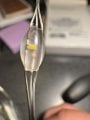
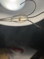
I can't make anything out from that image of the LED, sorry.

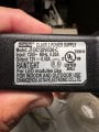
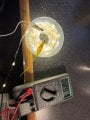
But I can see that the supply is 12 Volts not 6 as stated, but that is neither here nor there if the supply came with the string.

If that supply is unregulated then I would suspect that is the culprit in the second example, if it's regulated then I would look elsewhere.
 

Thread Starter

KT Depot

Joined Jan 15, 2025
9
I can't make anything out from that image of the LED, sorry.

But I can see that the supply is 12 Volts not 6 as stated, but that is neither here nor there if the supply came with the string.

If that supply is unregulated then I would suspect that is the culprit in the second example, if it's regulated then I would look elsewhere.
I will try to get a better picture.

A 6v adapter was for set up 1. A 12v was for set up 2. (I was going of off memory.)
 

ElectricSpidey

Joined Dec 2, 2017
3,326
Question:

In the first example how many bulbs were connected to a battery pack? (originally)

And which example was the pix of?

Can you take a pix of both bulbs and both supplies?
 

Thread Starter

KT Depot

Joined Jan 15, 2025
9
Question:

In the first example how many bulbs were connected to a battery pack? (originally)

And which example was the pix of?

Can you take a pix of both bulbs and both supplies?
I will have to count when I get home this evening.

The picture of the adapter and LED are from the second setup.
 

MisterBill2

Joined Jan 23, 2018
27,462
OK! My first guess is that the voltage is more than it should be, and that is why they are failing. My second guess is if they are getting wet, amazingly that damages some LED devices.
My third guess is mechanical flexing and something breaks. It may not show, it may not even come apart.
Those are guesses based on never seen any of it except for the photos. And a bit of experience with other LED stuff.
 

ElectricSpidey

Joined Dec 2, 2017
3,326
I can't see any resistor in that picture, so I can only guess that the system is relying on a voltage drop to prevent overpowering the LEDs.

The solutions to the issue may well be more trouble than starting over.

I don't know how invested you are in salvaging the current setup, but I would consider starting over with something more suited to modifying without having problems.

The solution to the first example could be placing resistors in series with each LED. (not the entire strip)

I'm at a loss as far as the second example.

There are LED strips on the market that are designed to be modified in length and are weatherproof, I just can't say how suitable they would be for what you need to do.

Sorry I can't be more help.
 
Top