Faint LED light...

Thread Starter

Externet

Joined Nov 29, 2005
2,672
Hello.
How to faintly keep on a 120VAC ceiling light with 1 mA or less, as to function like a night light ?

Tried 0.1μF/400V in parallel to the wall switch; nope. Tried a 1MΩ resistor, nope. Yet some LED light bulbs do it 'by themselves' in certain capacitive? wiring circumstances.
 

SamR

Joined Mar 19, 2019
5,535
I don't think you will find a way to excite a 120VAC incandescent filament with 1mA. Simply not enough energy to excite the electrons into emissions. Which is why we now have LEDs replacing incandescents. You would need a 0.12W bulb for 120VAC to excite it @ 1ma. Remember P=IE.
 
Since we have no information at all about the type of the " 120VAC ceiling light ", suggesting a suitable control is a bit of a challenge.
I start with the assumption that the TS is in the USA and has our standard 120 volt 60 Hz mains power, and that the ceiling light installation is the common mains powered with a series switch.

In my house, in several rooms, "standard" commercially available, series triac, light dimmers work with "common" LED bulbs of various kinds and brands. Those same dimmers also perform quite well with standard 120volt incandescent bulbs ofvarious ratings.
I have not attempted to install any experimental dimmers based on any hobby publication circuits, since there is no simple way to safely add such an external dinner circuit to the existing installation without a fair amount of effort to assure that it is safe and not a fire-hazard.
I did experiment with a hobby-class dimmer quite a few years back, with it installed in an external metal enclosure. That did work quite well to control a floor-standing lamp.
So it is possible to provide external dimming capability if a suitable enclosure is available.
What I have seen is that mostly the published circuits do not include any discussion as to thier safe and convenient installation and application. THAT is always the much more complex part of the project! The effort involved with suitable housing and application for industrial controls is similar in that aspect.
I have installed commercially available, made for permanent in-wall dimmers, in many locations, for both myself and friends, following standard practice and applicable electrical codes, as well.
CERTAINLY it is mandatory to know and understand just what must be done, and have the skill and resources to do it correctly and safely. Usually the instructions in many publications are both fairly accurate and quite incomplete, as far as details go.
 
Last edited:

BobTPH

Joined Jun 5, 2013
11,636
Goigle’s answer:
Option 2: "Scene Switch" or Dual-Mode LED Bulbs
If you do not want to change your physical wall wiring, you can achieve this simply by changing the light bulb.
    • How they work: These specialized bulbs use your existing, standard on/off toggle switch.
    • The mechanism: When you flip the wall switch on, the bulb lights up to 100% full power. If you quickly flip the switch off and back on within a couple of seconds, the bulb shifts into Night Light Mode(usually a soft 10% glow around the base or ring of the bulb).
 

bertus

Joined Apr 5, 2008
22,999
Hello,

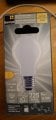
I have the same kind from sencys (a housebrand of the local hardware store praxis).
They have steps of 100 % , 50 % and 15 %.

20260912_202921.jpg

Perhaps there are simelar types on amazon etc.

Bertus
 

Thread Starter

Externet

Joined Nov 29, 2005
2,672
Perhaps no one read the thread title ? And where does the 'incandescent' and 'filament' and dimmer thing comes from ? It is for plain LED bulbs. How to make them barely emit light !
 
LED lamps meant for 120VAC will not be a good candidate as they have different guts.
as you already know SOME bulbs do emit reduced light output when switched off. if you are looking for a bulb with the ghost, try cheap ones (Dollarstore?).

another option is to stick with what MrChips proposed - use separate LEDs with own, low voltage PSU (USB charger).
 
Once again, my experience has been that some LED bulbs, 120VAC, 60Wand 100W equivalent, dim quite adequately when I use a "triac" type of dimmer from the local harware store.
BUT another brand of LED lights go into a "strobe-light" mode and start flashing. The flash rate increases as the dimmer is turned up, then eventually those bulbs deliver a constant full intensity light. Thus the conclusion must be that not all dimmers are the same, nor are all brands of LED bulbs identical. Some experimentation may be in order.

In one room at my house there is a 4-bulb ceiling light and those LED bulbs dim to just a pale yellow glow of the LED "filaments". Those bulbs are intended to be visible in that style of fixture, as they are clear glass, not frosted. When that fixture had incandescent bulbs installed, they could be dimmed to a very low level.
So it seems that there is a quite wide spread of performance in the realm of light dimmers. Some use an SCR while others use a TRIAC, is one difference I have seen.
 
Last edited:

MisterBill2

Joined Jan 23, 2018
28,154
I TOTALLY DISAGREE! For starters, modifying any part of an LED "Edison Based" 120 volt light bulb will require a very good magnifier and tools not commonly available to most hobbyists. AND it will require understanding that circuit hidden on the PCB inside the base of the bulb.
The fact is that there is a whole lot of variability among the commercially available wall-switch dimmers, and even greater differences between different LED-light-bulb circuits. No need at all to get into the fixture. BUT it WILL REQUIRE replacing the on/off switch with the right kind of dimmer-switch. Not all dimmer switches are the same.
AND A CAUTION: replacing a light switch in a wall-box is not a trivial task, especially in older houses. Older wiring that has rubber insulation will usually suffer it cracking if it is flexed. THAT adds a great deal of effort to the project.
 

MisterBill2

Joined Jan 23, 2018
28,154
Replacing a standard wall switch with a dimmer control requires a fair amount of understanding what one is doing. And mostly it is best to switch off the 120 volt mains power to that circuit, since a shock hazard from live wires exists.
One more caution: IF the place is wired with what is known as "BX" cable, forget it!! I speak from bitter experience!
 

Jon Chandler

Joined Jun 12, 2008
1,640
I TOTALLY DISAGREE! For starters, modifying any part of an LED "Edison Based" 120 volt light bulb will require a very good magnifier and tools not commonly available to most hobbyists. AND it will require understanding that circuit hidden on the PCB inside the base of the bulb.
As I stated in post #12, Big Clive has a wealth of knowledge about LED bulbs, and it's pretty clear you do not. Modern LED bulbs have very few components – a bridge rectifier, a smoothing capacitor, a linear line voltage current regulator, about 3 resistors and a series of LED packages (somewhere between 5 and 10), each containing multiple LED elements to bring the total Vf to approximately rectified line voltage.

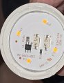
The prevalent circuit uses two resistors in parallel to set the linear regulator current. For whatever reason, conveniently for us (like somebody planned it this way), those resistors are typically in a ratio of about 3:1 ( I may be off in the ratio, but they are definitely NOT equal in value in most cases). The entire circuit is on a aluminum-backed pcb, front and center for the world to see when the plastic globe of the bulb is popped off.

Is the bulb too bright? Unsolder the larger resistor. Way too bright? Unsolder the smaller resistor. Usually, this provides about 2/3 original brightness or 1/3:eek:riginal brightness. The circuit arrangement is easy to see. Take off the plastic globe and there it is. Easy enough for my nearly 70 year old (WTF?!?) eyeballs to see without magnification.

No soldering iron? No problem. I am certain nearly everyone reading this forum has a pair of dikes/sidecutters. Just crush the body of the surface mount resistor.

Yes, I'm weird. I have been dissecting LED bulbs since the early days, replacing blown electrolytics to fix bulbs (not because I'm cheap, because I can), and taking bulbs apart just to observe the evolution in design. The cost optimization of modern bulbs is amazing, and most current designs are very similar.

How do I know the "cut out a resistor" scheme works? Because I have done it myself. The 3 bulbs (from Dollartree) above my bathroom vanity were way too bright for my taste. Snip. Snip. Snip. Ahhh, much better.

Perhaps a trip to Dollartree to buy a 2-pack of 60-watt equivalent bulbs ($1.25 – $1.50) would be informative? This discussion reminds me.... I am working on a 3D printed lamp, and the 60 watt bulb is too bright. I can fix that!

Screenshot_20260913_070547_Facebook.jpg

FB_IMG_1789308362734.jpg

FB_IMG_1789308378458.jpg
R1 and R2 are the resistors in question.

BTW – don't try this with GLASS LED bulbs!
 
Last edited:

Ya’akov

Joined Jan 27, 2019
10,294
I TOTALLY DISAGREE! For starters, modifying any part of an LED "Edison Based" 120 volt light bulb will require a very good magnifier and tools not commonly available to most hobbyists. AND it will require understanding that circuit hidden on the PCB inside the base of the bulb.
The fact is that there is a whole lot of variability among the commercially available wall-switch dimmers, and even greater differences between different LED-light-bulb circuits. No need at all to get into the fixture. BUT it WILL REQUIRE replacing the on/off switch with the right kind of dimmer-switch. Not all dimmer switches are the same.
AND A CAUTION: replacing a light switch in a wall-box is not a trivial task, especially in older houses. Older wiring that has rubber insulation will usually suffer it cracking if it is flexed. THAT adds a great deal of effort to the project.
You are wrong. There are only a few variants based on the common voltage dropper designs.

The construction of most LED bulbs makes accessing and modifying the boards easy.

There is probably just an SMD resistor that needs removal to make the bulb misbehave in the desired way.
 

Jon Chandler

Joined Jun 12, 2008
1,640
I sit corrected. In this particular DollarTree bulb – 60 watt equivalent daylight – there is the expected provision for two parallel resistors, but only one has been fitted. To reduce the intensity of this bulb, the existing resistor at RS1 would need to be unsoldered and replaced with a higher value resistor. Not a difficult change, but not as simple as cutting a resistor.

You can see the simplicity of the circuit. Bridge rectifier on the right. Linear regulator chip on the left. Smoothing capacitor is on the back to the contacts at the top. Line voltage contacts towards the bottom. Positions for two parallel current sense resistors RS1 and RS2. And finally, 7 LEDs, each containing multiple LED elements (I suspect 5 or 6 each to make Vf somewhat lower than the rectified line voltage).

CM260913-115507001.jpg
 
Top