Exponential amplifier using LM741

retched

Joined Dec 5, 2009
5,207
I dont think you read the link.

With a pull-up resistor and a 0 to +5V power supply, the output takes on the voltages 0 or +5 and can interface with TTL logic:
Useing a comparator with a internal reference voltage, you will get a 0 or a 1 at 5v. TTL which means TRANSISTOR TRANSISTOR LOGIC. Designed to do EXACTLY what you want to do. and about your quote:

If my input from the load cell is 0V when no load is applied and 20-50mV when a load is applied, comparing it to something like 5mV would STILL only give me 20-50mV output at most
You HAVE to take the information we give you and READ it.

Obviously you only read "using an opamp as a comparator" and not the rest.

Were here to help. This idea or application of yous has been being done for decades. You are insulting the people trying to help you by not taking the advice or SIMPLY blowing off the info given.
 

Ron H

Joined Apr 14, 2005
7,063
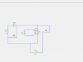
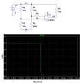
Here is a typical Wheatstone bridge with a comparator giving a digital output as the load cell varies from 119.9 ohms to 120.1 ohms. You will have to add your tare circuit, which should also be able to compensate for any input offset voltage that the LM393 has. You can add a transistor if you need to drive a bigger load, and we can show you how to do that.
 

Attachments

Ron H

Joined Apr 14, 2005
7,063
I dont think you read the link.


Useing a comparator with a internal reference voltage, you will get a 0 or a 1 at 5v. TTL which means TRANSISTOR TRANSISTOR LOGIC. Designed to do EXACTLY what you want to do. and about your quote:


You HAVE to take the information we give you and READ it.

Obviously you only read "using an opamp as a comparator" and not the rest.

Were here to help. This idea or application of yous has been being done for decades. You are insulting the people trying to help you by not taking the advice or SIMPLY blowing off the info given.
I don't feel the animosity that you do, but this is a classical case of a newbie coming up with a 'solution' before describing the big picture. It happens ALL THE TIME.
 

retched

Joined Dec 5, 2009
5,207
Sorry. I just watched 'old yeller' and my emotions are in turmoil. ;)

I do it FOR THE GOOD OF THE LAND!

No hard feelings summersab, I just didn't want you to have to pull your hair out looking for a solution while it is in front of you. Albeit not as obvious to you.

sometimes It is difficult for a new comer to trust the advice or info given, however it can only be as good as the problem is explained. In the future, you will have less of a hard time explaining the situation and executing the solutions offered.

I just found it odd that you started a new thread, as it seemed you did so because you didn't hear what you wanted in the first.

So,how bout them O's? (dont answer that)
 

SgtWookie

Joined Jul 17, 2007
22,230
Radio Shack carries the LM339; a quad comparator with open-collector outputs. You could use a LM111/311, or many other comparators - but Radio Shack just carries the quad LM339. It sounds like you want something right away, so get one of those.

Comparators operate just fine in open loop (no feedback), therefore has very high gain; much higher than a 741 opamp. However, it's usually desirable to have some feedback to the noninverting input for hysteresis (helping to preventing false triggers or oscillating near the trigger point).

The LM339 common mode range includes the negative rail. This means that you can sense right down to 0v using a single supply.

Did you have a Vcc voltage range in mind?
The LM339 can operate from a range of 2v-36v; however it would make designing a circuit much easier if you would choose a smaller range.
 

Thread Starter

summersab

Joined Apr 8, 2010
161
@retched, mainly, my problem is that I don't understand what a comparator is. I read the link, but as I said, my background is mechanical engineering, not electrical. It's like the computer science joke goes: PCMCIA stands for People Can't Memorize Computer Industry Acronyms. A lot of electrical jargon is over my head, and I just don't follow (TTL? Pull-up resistor? Credit to SgtWookie for talking stupid to me and defining his terms :) ). My apologies for starting a new thread - I found that I was having difficulty getting anyone to understand what I was trying to do.

On to the comparator. Still not really getting it. It probably isn't helping that the logic symbol for a comparator is EXACTLY the same as an op-amp, so I don't see (from a breadboarding perspective) how one goes about wiring one up. Also, I don't get how the logic behind them works. From Wikipedia:

In electronics, a comparator is a device which compares two voltages or currents and switches its output to indicate which is larger.
This is my understanding. A comparator takes two inputs, and the output is the larger of the two voltages. For instance, if I have 1V and 2V in, the output will be 2V. I'm not seeing how this helps me. If I have a comparator taking the input from my load cell bridge (which varies from 0-50mV or so), what is the other input to the comparator so that the output will yield 5V? From my understanding of the logic of a comparator, the other input would have to be 5V if I'm getting a 5V output. But in that case, the output will ALWAYS be 5V if it is compared to the 50mV input from my load cell:

V1....V2.. Vout
0mV 5V 5V
5mV 5V 5V
10mV 5V 5V
50mV 5V 5V

Does my babbling make sense? 5V is ALWAYS greater, so it's ALWAYS my output, right? I don't get how this fixes my problem. What I want is if one input is 0mV (or slightly negative, say), the output should be zero. If it's >0mV, the output should be 5V. I'm clearly missing something, here. So, yeah, a LM393 sounds great . . . but I don't get how it work or how to wire it up, and I'm clearly not Googling the right words.

Help . . . ?

**EDIT: For simplicity sake, scratch the bridge part for a moment. Can you just explain how a comparator (taking in two inputs, one from 0-50mV) can give the logic I need? The attachment given didn't really help explain how a comparator operates in this function.
 

retched

Joined Dec 5, 2009
5,207
If you get a comparator that has built in reference, It compares your input to its OWN reference, so no need for two separate inputs. Now if you wanted to compare two separate external signals, you have the ability to do that also.

Best to just keep trucking along and asking for help and clarification.

Using the in-tro-net searches can overwhelm many. give it a try, and ask. We can direct you to many links with more layman explanations.

Also remember, using an opamp is not the way to go. You will want to spend the 3 dollars and get a dedicated comparator with an on-chip reference that is TTL compatible. TTL basically means 0 or 5 outputs, low or high, rather than analog which can be everywhere in-between.
 

SgtWookie

Joined Jul 17, 2007
22,230
I'm going to go play and post if I have any more trouble. Sigh. Thanks for helping an electronics-impared individual. You all have a lot of patience . . .
You will not be able to use a 741 with a single voltage supply for your project, as the 741's common mode range is about 1.5v short of reaching either supply rail.

For example, if you are using a single 10v supply, the 741 can only "see" voltage inputs that are from 1.5v to 8.5v, for a total 7v range.

However, if you had both positive and negative supply rails (at least 5v each) then you could sense from -3.5v to +3.5v.

That is why I suggested using an LM339 comparator. It's common-mode range includes the negative rail; so you can use it with just a single supply.

You could also use an LM324 quad opamp (Radio Shack carries those) - but this is clearly a project that requires a comparator.

While one can often press an opamp into service as a comparator, it's sort of like using a hammer to install screws. You may get the job done, but it would've been so much better if you had used a drill and screwdriver.
 

Thread Starter

summersab

Joined Apr 8, 2010
161
Okay, so basically, I need to hook the +/- outputs of my bridge setup to the V1 and V2 inputs of a comparator that has Vcc = 5V. When V1 > V2, Vout = Vcc = 5V, and when V1 < V2, Vout = GND = 0V.

I tried this with a 741 (since that's what I have right now at 11:00 PM). Vcc = 9V, and when V1 > V2, Vout = 1.8V (instead of 9V). When V1 < V2, Vout = 700mV (instead of 0V). Also (and this might be a reason), I'm measuring the output as compared to the negative input V2. Should I be measuring it as compared to the GND supply to the chip? That's giving me a constant 8.7V no matter what my inputs. Is this because I'm using a 741 (and not a dedicated comparator)?

First thing I'm doing tomorrow is buying a comparator . . .

**EDIT: SgtWookie posted while I was typing this. See previous post - thanks, man!
 

SgtWookie

Joined Jul 17, 2007
22,230
Yep, you need an LM339.

Note that with the LM339, you will need to use a 1.5k pull-up resistor - from the output of the LM339 to +5V - in order to see an output.

You will also need to wire any unused inputs to ground.
 

Thread Starter

summersab

Joined Apr 8, 2010
161
Alright, so I wired up a LM339. All unused inputs are grounded. My Vcc is 5V as provided through a 5.1V Zener diode (I checked to make sure the Zener is wired correctly - the difference as measured from the Vcc pin to the GND pin is just under 5V). The output pin is connected to Vcc via a 1.5k resistor as mentioned in the previous post. When I connect 2V to the positive input and GND the negative input, I get an output of 700mV (measured from the output pin of the IC to the GND input of the IC). When I reverse the inputs, I get 113mV output. I also tried sending the negative input through a 1.5k resistor, but the values are identical. I'm getting exasperated - why isn't any IC I purchase behaving as expected? Shouldn't I be getting 5V SOMEWHERE?

Please. Help. White flag.
 

Ron H

Joined Apr 14, 2005
7,063
Do you have something else connected to the 339 output, like the base of a transistor?
Do you have a resistor between the zener and the power supply? If so, what is the value?
 

retched

Joined Dec 5, 2009
5,207
A schematic will be oh so helpful. Do you think you could manage? Or maybe a photo of the circuit?

Also, did you read the datasheet until it makes sense? Try using the sample circuit in the data sheet to understand whats up.
 

Thread Starter

summersab

Joined Apr 8, 2010
161
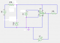
Attached is a schematic. The diode might be connected wrong in my diagram (lack of EE experience), but I've tested it with a voltmeter at the nodes - it's wired up. I figured out the hard way that if you reverse it, it gets burning hot. So, that to say, that part is right.

Nothing is connected to the LM339 except power, inputs, and grounds (to all unused inputs). Thoughts?
 

Attachments

Thread Starter

summersab

Joined Apr 8, 2010
161
Okay, this presents a typical "newbie" question. You threw in a "virtual ground." Why? Isn't that the same as tying everything to the black terminal? I mean, I'm not supposed to go pound a 6ft stake into the earth outside my house, right? K, just wanted to make sure. I'll test this in just a few.
 

retched

Joined Dec 5, 2009
5,207
On dc, a ground is the return path to the power supply.
AC it is the steak in the ground

GROUND is used as a 0v reference, but you could use a different reference if you were so inclined.

(And I would use a rod longer than 6 foot) ;)
 

Ron H

Joined Apr 14, 2005
7,063
Okay, this presents a typical "newbie" question. You threw in a "virtual ground." Why? Isn't that the same as tying everything to the black terminal? I mean, I'm not supposed to go pound a 6ft stake into the earth outside my house, right? K, just wanted to make sure. I'll test this in just a few.
I edited my schematic.
No, ground is just a reference node. It makes schematics much clearer. What you were really missing is the connection from the inputs to a point in the circuit that can supply current to the inputs. That doesn't have to be ground, but I understood you to say that one input is connected to zero volts, so that's the way I drew it.
And your zener was in the wrong place.
BTW, "virtual ground" has a couple of meanings, but this is not a virtual ground. Ground does not necessarily mean "earth".
 
Top