Exploring Ways to Introduce a 20-25 Second Transition Delay Between Red and Green LEDs in My Circuit Simulation.

ericgibbs

Joined Jan 29, 2010
21,541
Hi AM,
Have you considered using the transition to trigger a 555 Monostable for say 20 secs.
Post your best attempt of a circuit.
E
 

Papabravo

Joined Feb 24, 2006
22,111
You can use a behavioral source with the idt() function to make a time to voltage conversion. Then you use the voltage to measure a precise time interval. That gets you the simulation part and converting that to a circuit will finish things off. Funny they don't allow you to use a comparator, since that would be the natural part to use.
 

dl324

Joined Mar 30, 2015
18,449
Yeah I am allowed to use 555 timer and the only op amp that I am allowed to use except LM324 is LM741
Your first post showed you using LM339. Then you started using LM324 in LTspice, which won't work because they don't have open collector outputs like LM339.

If you have no clue how to implement the circuit, at least give us a block diagram showing the steps you'd take.

It's probably time for you to post the complete text for the problem.
 

Thread Starter

AMOGELANG

Joined Oct 16, 2022
20
Hi AM,
Have you considered using the transition to trigger a 555 Monostable for say 20 secs.
Post your best attempt of a circuit.
E
Thank you for your suggestion! I appreciate your input. However, I've been encountering a specific challenge with the 555 Monostable circuit in my application. Most of the tutorials I've found online demonstrate how to use a 555 in monostable mode to control the time an LED stays on. In my case, I need the LED to remain on continuously until I change the voltage, and I only want a delay when the voltage changes from -6 to -5 or from 5 to 6.

To clarify, I'm aiming for a situation where the LED remains lit while the voltage is stable between -6 and 6 volts, and it only turns off or has a delay when there's a voltage transition within the range of -6 to -5 or from 5 to 6 volts. This requirement seems a bit different from the standard 555 Monostable setup, which typically triggers a delay when the input signal goes high.
 

Thread Starter

AMOGELANG

Joined Oct 16, 2022
20
You still show the op-amp outputs shorted together. They will fight each other.
Thank you for your concern. In the circuit I'm designing, I'm using a window comparator configuration, which typically has a single output representing whether the input signal falls within a specified voltage window. This configuration intentionally connects the op-amp outputs together to create this single output. It's not a case of the op-amp outputs fighting each other; rather, it's part of achieving the desired functionality of the window comparator.
 

Thread Starter

AMOGELANG

Joined Oct 16, 2022
20
You can use a behavioral source with the idt() function to make a time to voltage conversion. Then you use the voltage to measure a precise time interval. That gets you the simulation part and converting that to a circuit will finish things off. Funny they don't allow you to use a comparator, since that would be the natural part to use.
Thank you for your suggestion. Just to confirm, are you suggesting the use of a microcontroller for this time-to-voltage conversion, or is there a specific component or method you have in mind for implementing it within a circuit?
 

Thread Starter

AMOGELANG

Joined Oct 16, 2022
20
Your first post showed you using LM339. Then you started using LM324 in LTspice, which won't work because they don't have open collector outputs like LM339.

If you have no clue how to implement the circuit, at least give us a block diagram showing the steps you'd take.

It's probably time for you to post the complete text for the problem.
Thank you for your observations. I should clarify that initially, I posted a circuit using LM339 because Tinkercad doesn't have LM324 available for simulation. I used LM339 as a substitute for simulation purposes, fully aware that in my actual circuit implementation, I intend to use LM324 without a pull-up resistor. The intention was to get a rough approximation of the behavior I expected to see when using LM324.

I appreciate your concern regarding the transition from LM339 to LM324, particularly the differences in their open collector outputs. I will ensure to address these differences and challenges when implementing the final circuit.

Now, regarding the specific functionality I'm looking to achieve, here's the updated requirement: I need to introduce a delay so that when the voltage changes from -6 to -5 or from 6 to 5, a red LED must remain on for approximately 20-25 seconds before turning off, and after that delay, a green LED must turn on.

I'm currently seeking input and suggestions on how to implement this specific delay functionality in my circuit. If you have any hints, ideas, or insights that might help me achieve this delay, I'd greatly appreciate your input. It's the final piece of the puzzle I'm working on, and any guidance would be valuable.
 

Thread Starter

AMOGELANG

Joined Oct 16, 2022
20
Hi AM,
A simple diagram showing the LED operation.

I assume you want the LED to come back On, IF the Voltages return to +6v or -6v ?

E
Thank you for your response and your willingness to assist with my circuit design. To clarify, when the voltage level transitions from -6 to -5 or from 6 to 5, I want the RED LED to be on for a delay of 20-25 seconds. Immediately after this delay has elapsed, I want the GREEN LED to turn ON.

I hope this clarifies the behavior I'm aiming to achieve, and any insights or suggestions you have on how to implement this specific delay would be greatly appreciated.
 

Thread Starter

AMOGELANG

Joined Oct 16, 2022
20
Thank you for your response and your willingness to assist with my circuit design. To clarify, when the voltage level transitions from -6 to -5 or from 6 to 5, I want the RED LED to be on for a delay of 20-25 seconds. Immediately after this delay has elapsed, I want the GREEN LED to turn ON.

I hope this clarifies the behavior I'm aiming to achieve, and any insights or suggestions you have on how to implement this specific delay would be greatly appreciated.
I want to introduce a delay mechanism for when the circuit switches from the red LED to the green LED. Here's what I'm looking to achieve:

When the system is set to transition to the green LED, I'd like the red LED to remain on for a period of 20 to 25 seconds before the green LED is activated. Simultaneously, the red LED should turn off. However, I'm unsure of how to implement this specific delay in my circuit design.
 

Alec_t

Joined Sep 17, 2013
15,149
This configuration intentionally connects the op-amp outputs together to create this single output.
No, it doesn't, since op-amps have push-pull outputs. But comparators which have open-collector/drain outputs can be wire-ORed together. You can, however, connect op-amp outputs via respective diodes to a common node if you need the OR function.
 

ericgibbs

Joined Jan 29, 2010
21,541
This requirement seems a bit different from the standard 555 Monostable setup, which typically triggers a delay when the input signal goes high.
Hi AM,

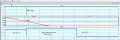
It is possible, this is a timing plot of a circuit along the lines I suggested, I cannot post the actual circuit.
I have shortened the Mono time to simplify the test.

Post your circuit.:)
E
EG57_ 1205.png
 

Papabravo

Joined Feb 24, 2006
22,111
Thank you for your suggestion. Just to confirm, are you suggesting the use of a microcontroller for this time-to-voltage conversion, or is there a specific component or method you have in mind for implementing it within a circuit?
No! In the simulation you should have available a component known as a behavioral voltage source. If you make it generate a linear ramp with a slope of 1V/sec, then you have a time to voltage converter. The idt() function is LTspice is perfect for this. When you get this working you can convert the behavioral source to an actual circuit. The point of simulation is understanding.
 

ericgibbs

Joined Jan 29, 2010
21,541
Hi AM,
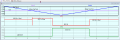
This simulation plot shows the LED states for above and below the 5V ref.
Note for testing I have shortened the delay time.
E
EG57_ 1206.png
 

ericgibbs

Joined Jan 29, 2010
21,541
hi AM,
The circuit for the above sim uses your two LM324, a 555, & 3 general purpose diodes.

Post your best circuit, and we can work through it.

E
 
Top