Experiencing failures in the field. Possible power surges.

Thread Starter

morzh

Joined Jan 18, 2017
38
We have been experiencing this problem. 99% of it occurs in Asia. We have our device deployed in about equal numbers in Europe, Asia and Americas.

We have a Meanwell desktop GST series power supply feeding the unit. The Power supply output is 12V/11.5A (we do not need this much but the start inrush of a DC motor of the vacuum pump we use makes a lesser supply hiccup, hence the rating; otherwise the unit normally draws under 2A).
The 12V feeds two POLs, both are the same Artesyn 12V adjustable supplies, LDO03C-005W05-HJ (up to 13.8V Vin), producing 3.3V and 5V, not especially heavily loaded (3A-rated units).

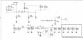
The 12V input is protected by SMBJ13A (or now SMBJ15A, after we had the failures) transorbs (D3 and D8 in the attached circuit diagram). These are 600W-rated. At this point the manufacturer is Fairchild (On Semi).
In the attached sch you can see the input; pins 1,3 and 5 eventually connect to the same 12V, so effectively connected to the same Meanwell 12V output.

Recently we have been experiencing large scale failures (In Asia) of the Transorbs. Up 'till recently in has been almost exclusively D3, which I attributed to the higher rated fuse (F3), with the fuse remaining intact (the power supply goes to hiccups and does not burn the fuse). Upon changing D3 the boards would resume operation. The last couple of cases were different: it took out D8 and the F1 fuse. And, upon changing them, the board did not go back on line (I have not gotten the boards back yet to determine with 100% being sure the reason), which is indicative of the Artesyn POL(s) having been damaged.
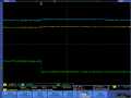
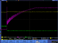
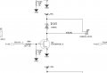
This all is indicative of the bad power surges, but the unit has been tested in the certification lab for immunity, plus a third party tested the power supply with standard active load and the transorb using ECAT model E510A 1.2/50µs, 8/20µs combination waveform, 500A/1kV pulses (+/-90 degrees and such) and they could not fail the transorb. Now they are testing it with the only serious inductive load we have (a vac pump, 12V/1.6A motor) which is connected with the freewheeling diode across and which I looked at at some point and I failed to see any voltage surge across it. (the connection is shown in the second circuit attached).

I also have to add that the previous model used a much heavier power supply from TDK-Lambda (really overbuilt) and we never saw this kind of failures before, nor did we use any transorbs.

Has anyone experienced a similar problem, and if yes, was it with a particular power supply brand and in what part of the world?

Best

Mike.
 

Attachments

ebp

Joined Feb 8, 2018
2,332
I'll try to look at this more closely later and give it some more thought.

I would suggest testing the dynamic performance of the Meanwell power supply - step change in input voltage, not just brief impulse superimposed on the normal AC input, and also step change in output current over the allowable range of input voltage. Getting very good DC regulation with a switcher is comparatively easy, but accomplishing good dynamic performance is another matter and something that tends to be glossed over in the specifications.

At the power level of the supply in question, there is some chance that it is a flyback converter operating in continuous inductor current mode. Flyback converters operated this way suffer from a "right half-plane zero" in the transfer function. A RHP zero can't be compensated for and the typical way of dealing with it is to reduce the bandwidth of the control loop to sort of push it out of the way. This makes dynamic performance poor, which can lead to undershoots and overshoots at the output.

My very first encounter with Meanwell power supplies was to diagnose a manufacturing problem that turned what should have been something that increased reliability into a something that greatly reduced reliability. They meant well, they just didn't pull off their intent. It was a new experience - the only time I've ever actually been inside a giant video monitor and had to climb several segments of ladder to get to the location of the problem.
 

Thread Starter

morzh

Joined Jan 18, 2017
38
EBP

Thanks for replying

The GST160A12 is the supply,
http://www.meanwellusa.com/productSeries.aspx?i=26&c=6#tag-6-26

I am not sure if it is a flyback or a forward converter. I once repaired a Meanwell, but that was a 48V output big unit powering a Telecom Switch shelf. We had more than one failure (in the lab - in the field in Telecom CO the Verizon or other baby Bells, or India Telecom obviously use some huge thingies, like stacks of Hendries etc). But I never had any experience with their Desktop converters.

I am considering swapping it for a TDK-Lambda unit which looks like its twin brother, so I hope they are not made at the same factory and re-labeled, but my experience with Lambda so far has been good.
However at this point I am not sure what's at play here, and if what we are seeing is surges or something else, like what you said (would that be enough to take out the transorb though? The part is 28A Ipeak tested at 10/1000 REA waveform that allows 600W peak, clamping at 21.5V, standby voltage is 14.4V minimum so it has to be exceeded in the first place).
 

Hymie

Joined Mar 30, 2018
1,284
It is interesting that you are seeing virtually all failures in Asia – if mains borne noise is the culprit I would expect many others to be reporting this problem.

One expensive fix (and not easy to retrofit) I can suggest (if it is due to mains spikes) is to include inductors in-line with the fuses.

But I am suspicious that the diode failure might actually be due to electrical noise from the dc motor. I have seen large voltage (ac) spikes due to the operation of some dc motors – so it might be the forward diode conduction of this motor noise that is killing them. Your diode D16 is only preventing electrical noise in one polarity.

I suggest you take a close look at the voltage across the motor with a scope – if excessive noise is present, an easy fix is to place an appropriately rated capacitor across the motor.
 

ebp

Joined Feb 8, 2018
2,332
The power supply you are using has active power factor correction, so the DC input to the down-switcher is quite accurately pre-regulated. PFC also puts a substantial inductor between the positive output of the bridge rectifier and the DC filter capacitor, and usually has quite generous additional common mode and differential mode inductive filtering together with capacitors across the line at various points to counter EMI. All of this is generally quite good at keeping fast transients out and rejecting variation in AC line voltage.

I don't see the motor as being a very likely culprit since you don't see the failures in other locations.

I think your doubt about the ability of the power supply to take out the transorbs is reasonable. The only thing I see as a possibility, and it now seems less likely given the fact the supply has PFC, is that the output of the supply is somehow going too high for long enough to cause the average power in the transorbs to exceed what they can handle and causing them to fail short-circuit. The SMB package is small and without substantial copper foil connected to it will get very hot with modest power. 200 mA of sustained current at the lowest conduction voltage of the devices in question might be enough - but I just can't see the power supply voltage staying sufficiently high for sufficiently long to be an issue, even with poor dynamics.
 

Thread Starter

morzh

Joined Jan 18, 2017
38
Well

here are two files showing 12V across the surge absorber (well, it is the same everywhere I looked, low inductive planes) when the pump start and stops.

Then there are files showing start/stop with the pump current as measured with Tektronix current P4062 50MHz probe (2A/div).
The Yellow trace is 12V power, the blue - 12V right at the pump, the Green is current at 2A/div and the Purple is the Negative of the pump (the one driven by FET).
 

Attachments

Last edited:

ebp

Joined Feb 8, 2018
2,332
Unless I'm missing something, I don't see anything there even remotely likely to be problem. The power supply dynamics, while not spectacular at motor start-up, are good and very clean. There is no sign of any overshoot when the motor current is turned off, and the slight dip at motor startup is certainly not a problem. The purple ringing might be be undesirable in terms of EMI/RFI, but it isn't going to do anything to the transorb.

Without knowing some more details I can't see how it might occur, but could there be any chance that improper grounding somewhere might allow current totally unrelated to your circuit could find its way through the transorbs? Is there any chance lightning might be a problem?
 

Thread Starter

morzh

Joined Jan 18, 2017
38
ebp:

right you are, I do not see anything remotely likely to the problem either. Ringing does not get anywhere outside that wire which is where the collector (well, Mosfet's drain in this case) drives the negative of the pump. The device got certified for CE/FCC with flying colors, nothing really that was bad enough to show any significant peaks. Methinks the ringing could be the mosfet + whatever the negative pump wire connected to inside the pump relative to the GND capacitance forming a tank with the wire plus that same stuff inside the pump inductance.
The turn-off is very benign, showing about 0.4V (Schottky Vf) short-lived bumpie. The current goes linearly to zero when that happens.

Lightning? of course it could. But then....it's too many (12 at this point) of the cases vs people having other equipment sitting around plugged into the same outlet that is ok.
 

Thread Starter

morzh

Joined Jan 18, 2017
38
One more thing:

The AC Outlet Earth wire inside the DC plug is connected to the "-" output terminal. Which is often the case.
I looked at the TDK-Lambda unit, with exact same connector and parameters, and the shell of the connector that is connected to the AS Earth is also connected to "-" output of the 12V.

This said, when scope is put across the surge absorber, if anything whatsoever is there that can trigger it, this will cause the voltage spike across it we will see. The triggering occurs at 14.4 V minimum. All we see is 12.4V during the pump stopping.
 

Hymie

Joined Mar 30, 2018
1,284
One more thing:

The AC Outlet Earth wire inside the DC plug is connected to the "-" output terminal. Which is often the case.
I looked at the TDK-Lambda unit, with exact same connector and parameters, and the shell of the connector that is connected to the AS Earth is also connected to "-" output of the 12V.

This said, when scope is put across the surge absorber, if anything whatsoever is there that can trigger it, this will cause the voltage spike across it we will see. The triggering occurs at 14.4 V minimum. All we see is 12.4V during the pump stopping.
Are the voltage/current measurements you have recently posted, measured on a failed unit - which was subsequently repaired?

If not, I would suggest you repeat the measurements on such a unit that might reveal some circuit transients causing the failures.
 

Thread Starter

morzh

Joined Jan 18, 2017
38
No, the transients were taken on a new unit.
Given the frequency of occurrences, I don't believe that would make a difference in measurement.

One more thing that makes me thing so, the unit at some point was fitted with a different pump (vane vs rotary) due to the size and consumption considerations. Then the old pump came back: the customers did not like the new vibration pattern. The pumps exhibit different patterns of behaviour, both start inrush and consumption current waveshape.
So, we see units with both pumps amongst the ones that failed.

This measurements was concerned with the pump pattern (this one is for the older type pump: it is heavier and consumes more power).
 

Thread Starter

morzh

Joined Jan 18, 2017
38
So I thought about the testing: I am planning to buy a day in a cert lab and using an ECAT surge generator equipment to conduct an "accelerating aging" test, using 3-4 similar power supplies that I have and a SMBJ13A transorb connected to each of them, zapping it continuously with surges. He who croaks first gets the prize. Then the rest keeps being zapped until either nothing happens, or they start dropping out one by one, or.....
Of course, even that is not 100% conclusive as we are trying to induce a failure which may or may not be the root cause of what's been going on.
 

Hymie

Joined Mar 30, 2018
1,284
So I thought about the testing: I am planning to buy a day in a cert lab and using an ECAT surge generator equipment to conduct an "accelerating aging" test, using 3-4 similar power supplies that I have and a SMBJ13A transorb connected to each of them, zapping it continuously with surges. He who croaks first gets the prize. Then the rest keeps being zapped until either nothing happens, or they start dropping out one by one, or.....
Of course, even that is not 100% conclusive as we are trying to induce a failure which may or may not be the root cause of what's been going on.
As part of CE marking, the Meanwell & TDK-Lambda power supplies will have both undergone mains-borne fast transient testing, demonstrating compliance with the EMC Directive.

I’m sure both Meanwell & TDK-Lambda would be willing to supply a copy of the EMC test report for their supplies – I have seen many such reports (supplied by third-parties through my work).
You might like to peruse the reports before spending thousands on your own testing.

TDK-Lambda has a manufacturing/R&D facility in Ilfracombe (UK) – you could contact their technical department to discuss your failures and possible causes.
 
Top