Equation to find a absolute value of the sine wave at any given angle

Thread Starter

cts_casemod

Joined May 14, 2013
35
Hi folks,

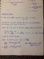
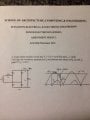
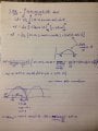
I am studying phase angle control and I need to derive a simple equation that allows me to calculate the angle of a sine wave at a particular voltage, to trigger a triac.

For example: say i am given a RMS voltage of 240V and I wish to find the angle at which the instantaneous voltage is 65V.

I know at 0pi the voltage is zero and at pi is 240*(sqroot2) or 339V. But how do i find the values in between?

Many Thanks
 

MrAl

Joined Jun 17, 2014
11,342
Hello,

Use the inverse sin function. Sometimes written as "asin(y)" or as "sin^-1(y)".

This is a multi valued function however so you have to know what quadrant you want the solution for.

So with a 339v peak you would do:

angle=asin(65/339)
for angle in radians, and another solution at angle2=pi-angle, or

angle=asin(65/339)*180/pi
for angle in degrees, and there will be another solution at angle2=180-angle.
 
Last edited:

Thread Starter

cts_casemod

Joined May 14, 2013
35
Hello,

Use the inverse sin function. Sometimes written as "asin(y)" or as "sin^-1(y)".

This is a multi valued function however so you have to know what quadrant you want the solution for.

So with a 339v peak you would do:

angle=asin(65/339)
for angle in radians, and another solution at angle2=pi-angle, or

angle=asin(65/339)*180/pi
for angle in degrees, and there will be another solution at angle2=180-angle.

Thank you very much.
Is there also a simple expression to calculate the peak current when an inductor is present?
 

MrAl

Joined Jun 17, 2014
11,342
Thank you very much.
Is there also a simple expression to calculate the peak current when an inductor is present?
Hi,

Well, it depends on what kind of waveform you expect to see with the inductor. If it is just a sine wave then it is simpler:
Ipk=Epk/(w*L)

where w=2*pi*f, f is the frequency in Hertz.

Are you working with sine waves (ie AC voltage) ?
 

Thread Starter

cts_casemod

Joined May 14, 2013
35
Hi,

Well, it depends on what kind of waveform you expect to see with the inductor. If it is just a sine wave then it is simpler:
Ipk=Epk/(w*L)

where w=2*pi*f, f is the frequency in Hertz.

Are you working with sine waves (ie AC voltage) ?
Yes, AC mains.

I am given some circuit parameters for a rectifier circuit with a series inductor.
I know that the currents starts flowing when the instantaneous sine wave voltage is larger that the capacitor voltage. In such scenario the diodes are forward biased and current flows from the source to the capacitor.

I am, however, given a circuit with a series inductor. In such case the current starts increasing at the same point, however the inductor is charged rather than the capacitor. I also know that the peak current is reached when the supply voltage goes below the capacitor voltage in which the inductor now tried to opose the change in current and acts as a voltage source of negative polarity adding to the mains frequency to keep the current flowing into the capacitor.

What I need to calculate is what is the maximum value of the current and when does the inductor become completely discharged, effectively not supplying any more load to the capacitor.I hope this diagram can clarify, otherwise please ask.


MrAl

Joined Jun 17, 2014
11,342
Hello again,
Yes, AC mains.

I am given some circuit parameters for a rectifier circuit with a series inductor.
I know that the currents starts flowing when the instantaneous sine wave voltage is larger that the capacitor voltage. In such scenario the diodes are forward biased and current flows from the source to the capacitor.

I am, however, given a circuit with a series inductor. In such case the current starts increasing at the same point, however the inductor is charged rather than the capacitor. I also know that the peak current is reached when the supply voltage goes below the capacitor voltage in which the inductor now tried to opose the change in current and acts as a voltage source of negative polarity adding to the mains frequency to keep the current flowing into the capacitor.

What I need to calculate is what is the maximum value of the current and when does the inductor become completely discharged, effectively not supplying any more load to the capacitor.I hope this diagram can clarify, otherwise please ask.

So your circuit is a rectifier circuit as pictured?
Is there anything about it that is known, such as resistor value, cap value, inductor value?
What is the min and max currents that you intend to use?
Do you know any of the transformer characteristics?

The current in a rectifier circuit with an inductor is different than in a circuit with just a rectifier and capacitor. Current flows more often due to the inductor, not just when the cap voltage becomes lower than the sine wave voltage. This also means that the inductor may never be completely 'discharged'.
We can model this circuit, but it will help to know the answers to the above questions.
 

t_n_k

Joined Mar 6, 2009
5,455
What I need to calculate is what is the maximum value of the current and when does the inductor become completely discharged, effectively not supplying any more load to the capacitor.I hope this diagram can clarify, otherwise please ask.
Also a further question ....
Given your earlier post about phase control - Is this for a controlled rectifier case or the simple full wave rectifier shown in the diagram?
 

Thread Starter

cts_casemod

Joined May 14, 2013
35
Also a further question ....
Given your earlier post about phase control - Is this for a controlled rectifier case or the simple full wave rectifier shown in the diagram?

No, this is just for a standard rectifier. The attached photos show the details I'm given along with a mathematical resolution.
In real life I've designed PFC circuits and switch mode power supplies and all the right parameters were given such as maximum inductor current, continuous mode, discontinuous, current rise times..

Academically, they kind of simplify some of these things, but fail to relate this to what is actually happening. For example, without knowing the current, capacitor ESR, etc, these calculations may well be invalid which makes it a bit harsh to try and simulate something in an attempt to understand whats going on.

I would be grateful if someone could help me "make sense" of the provided information.
 

Attachments

Last edited:

t_n_k

Joined Mar 6, 2009
5,455
It's not clear where your concerns lie. Given you gave an analysis at hand (albeit for a rather different topology with respect to the inductor position) it would help if you could refer to specific points in the analysis as the basis for discussion.
 

MrAl

Joined Jun 17, 2014
11,342
Hello again,

Let me see if i can help a little here.

If you are uncomfortable with the inductor on the AC side you can put it on the DC side as long as the inductor conducts in a discontinuous mode which i think it does. But it doesnt matter that much, on the DC side it just conducts in the same direction all the time, and since we only need one half cycle solution it doesnt matter a heck of a lot anyway.

In this new drawing (and new circuit) it looks to me that they are actually asking you a simpler question by giving you some partial solutions already.

The biggest giveaway is the DC voltage, which is 150v as stated. That means they want you to consider it constant, and that eliminates the value of the capacitor except to think of it as very large...large enough to keep the DC voltage nearly constant all the time regardless of load. That also tells us that iC equals zero.
The other clue is they state an equality of areas in the regions shown.
The third clue is the peak of the rectified sine is labeled as "sqrt(2)*Vs", which means the diodes are considered ideal.
The fourth clue is they show the load current as "iLoad" with the direction of current flow indicated with the arrow.

So solving for Angle b is easy because it's just the time where the input rectified sine coincides with the DC voltage, which is a no brainer.
To get the second angle, Angle f, you'll have to find the solution to the time when the AREA of the DC voltage minus the sine from the second coincidence of the DC voltage and sine (beyond 90 degrees) and the time when Angle f equals the area shown as Area A, so you'll need to calculate the area of the DC voltage minus the sine and then solve for the time when the areas are equal, and that gives you Angle f.

Since the fourth clue is a variable i suppose they want you to calculate id symbolically.

Overall i think it is more fun to calculate the Fourier series for the full wave rectified sine, then apply it to the RLC filter made up of some load R and the L and a smaller value of C, then plot the resulting output voltage and/or inductor current, etc.
 
Last edited:

Thread Starter

cts_casemod

Joined May 14, 2013
35
Hello again,

Let me see if i can help a little here.

If you are uncomfortable with the inductor on the AC side you can put it on the DC side as long as the inductor conducts in a discontinuous mode which i think it does. But it doesnt matter that much, on the DC side it just conducts in the same direction all the time, and since we only need one half cycle solution it doesnt matter a heck of a lot anyway.

In this new drawing (and new circuit) it looks to me that they are actually asking you a simpler question by giving you some partial solutions already.

The biggest giveaway is the DC voltage, which is 150v as stated. That means they want you to consider it constant, and that eliminates the value of the capacitor except to think of it as very large...large enough to keep the DC voltage nearly constant all the time regardless of load. That also tells us that iC equals zero.
The other clue is they state an equality of areas in the regions shown.
The third clue is the peak of the rectified sine is labeled as "sqrt(2)*Vs", which means the diodes are considered ideal.
The fourth clue is they show the load current as "iLoad" with the direction of current flow indicated with the arrow.

So solving for Angle b is easy because it's just the time where the input rectified sine coincides with the DC voltage, which is a no brainer.
To get the second angle, Angle f, you'll have to find the solution to the time when the AREA of the DC voltage minus the sine from the second coincidence of the DC voltage and sine (beyond 90 degrees) and the time when Angle f equals the area shown as Area A, so you'll need to calculate the area of the DC voltage minus the sine and then solve for the time when the areas are equal, and that gives you Angle f.

Since the fourth clue is a variable i suppose they want you to calculate id symbolically.

Overall i think it is more fun to calculate the Fourier series for the full wave rectified sine, then apply it to the RLC filter made up of some load R and the L and a smaller value of C, then plot the resulting output voltage and/or inductor current, etc.
Yes, that's correct. In fact, I see no problem if the current was continuous. After all, the inductor only takes care of the ripple which is an AC signal, regardless if it is before or after the diodes.

I want to find the area of part b which as you mentioned = part A.
I am aware I could integrate to find the area, but I am looking for some simpler equation to find where (and if) the current reaches zero.

Any way this could be calculated? Regards
 

MrAl

Joined Jun 17, 2014
11,342
Hi,

Well this integration should not be too difficult because it's just a sine wave, right? Try it before you give up on it.
You know where the start point is, and you know what the area is (A), so you can solve for the point in time where A=B.
 

t_n_k

Joined Mar 6, 2009
5,455
I am aware I could integrate to find the area, but I am looking for some simpler equation to find where (and if) the current reaches zero.

Any way this could be calculated? Regards
One heuristic approach from the perspective of the inductance required to give operation on the boundary between CCM and DCM, which appears to work for an ideal rectifier with your choke input filter topology is described as follows...

For a DC output voltage Vd, load current Id, peak single phase AC input voltage Vm at line [angular] frequency \(\text{\omega}\) radians / sec, the inductance giving the boundary condition would be

\(L=330\frac{V_d}{\omega I_d} \ mH\)

where

\(V_m=1.57V_d\)

is the 'required' peak AC voltage.

I haven't confirmed this works over a wide range of conditions but you might wish to test the validity. One also has to assume the filter capacitor is sufficiently large that the load voltage ripple is relatively insignificant.
 

MrAl

Joined Jun 17, 2014
11,342
Hello again,

Well i just tried this with a different frequency of 50Hz so i wouldnt give the answer away if i stated the result and also 50Hz makes the equation a little neater because 2*pi*50=100*pi :)

Calling the time of the first coincidence of 150v and the sine wave t1 and the second coincidence t2, the place where the area is equal i then call t3 and i get:
t3=0.00813701 seconds (to 8 decimal places as shown)
for the first half cycle after steady state has been reached.

This wasnt that difficult to calculate because it's just a couple areas to calculate, The third time t3 was a little harder to calculate because it had to be done numerically, but that was made easier by simply doing a plot first of the integrated difference minus the first area A and noting when this went through zero.

We can go through it step by step if needed i guess.

Oh yeah BTW, the theory behind this area equality is based on the volt seconds of the inductor viewed as an energy. For a lossless inductor, the volt seconds during charge equals the volt seconds during discharge if discharged back to the original level before it was charged. Another well known example of this is when a relay coil is energized and then de-energized and some sort of clamping device is used to eat up the discharge energy, like a diode. The time to discharge faster with a higher voltage drop device can be estimated by noting the ratio of the volt seconds for each discharge method and calculating the ratio.

As a final note, at 50Hz the load current comes out to a constant:
10.686 amps (to 5 significant digits as shown).
 
Last edited:
Top