Equalizer gain: unity or A>1?

Thread Starter

AmiguelS

Joined Jun 25, 2014
20
Hello people!
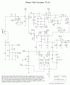
Once again I'm in need of you're wise advices. I have built this circuit below on a vero board, I built two them, the lates to offer to a friend. You may recognize the circuit, it's know as a TS-808 Tubescreamer (guitar pedal).

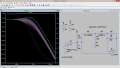
Te problem is the following, The section highlited in red is giving me diferent results on each of the builds, the first one is giving me gain>1 in a specific frequency and the second one is giving me unity gain at the same frequency (i'm talking low frequencies ). I haven't been able to understand that equalization circuit and so I don't know which one of the two has a problem, the one with unity gain or the one with A>1.


Can you shed some light on this matter please?

Thank you in advanced!


Circuit
 

tindel

Joined Sep 16, 2012
936
Are you sure the trim pots are positioned the same - resistance wise - not location. A quick analysis of the circuit I did in spice shows that that the tone control attenuates and provides gain depending on where the pot is trimmed to.

That sure is a weird amplifier configuration one I haven't seen before... weird.
 

Attachments

tindel

Joined Sep 16, 2012
936
Also tantalum caps can vary a lot from the specified value (all caps, not just tantalums) this can cause differences in operation.
 

to3metalcan

Joined Jul 20, 2014
260
I think it's a differential amplifier, just weirdly laid-out...you're feeding a low-passed version of the signal to the inverting input and the straight signal to the non-inverting one, and the cut/boost results from the difference between the two.

I never understood why they used emitter-followers on these pedals instead of just using a quad op-amp for the whole thing (actually, if you're using true bypass, like this schematic, instead of the buffered bypass, I don't really understand the point of including the emitter-followers at all...)

I like the asymmetrical clipping on AmiguelS' schematic. That'll probably sound more interesting than the TS-9 schematic.http://forum.allaboutcircuits.com/member.php?u=242369
 

#12

Joined Nov 30, 2010
18,224
I never understood why they used emitter-followers on these pedals instead of just using a quad op-amp for the whole thing (actually, if you're using true bypass, like this schematic, instead of the buffered bypass, I don't really understand the point of including the emitter-followers at all...)
See post #2 :D
 

Thread Starter

AmiguelS

Joined Jun 25, 2014
20
Are you sure the trim pots are positioned the same - resistance wise - not location. A quick analysis of the circuit I did in spice shows that that the tone control attenuates and provides gain depending on where the pot is trimmed to.

That sure is a weird amplifier configuration one I haven't seen before... weird.

I ran that simulation in Multisim and for low frequencies (<100Hz) the gain is of about -1dB. From that point on it varies with tone control.

Situation point: Second build works as simulation predicts, first build works in different way. First build sound WAY better :confused: I guess I'll have to trace the mistake in build one and repeat it in build two...
Any ideas on what mistake would increase the gain at low frequencies? I'm talking build mistake as short circuit on a track or something, not component value wise. Would a blown cap (the one attached to the pot) cause this, maybe from soldering overheat? It's not visibly blow, but maybe the inside is?
 

to3metalcan

Joined Jul 20, 2014
260
Tantalum caps are rabidly polar and blow very easily (not always visibly) if they're put in backwards even briefly. See if decreasing the value of the cap connected ti the pot gets you the results you're looking for.
 

Thread Starter

AmiguelS

Joined Jun 25, 2014
20
Nope, that doesn't do it. I cant seem to be able to increase the overall gain of the configuration. If I find a way of short circuiting or miss connecting something that leads to a higher gain throughout the whole spectrum, that's probably the mistake present on the board, but I can't seem to find such a thing. Increasing the feedback resistor does nothing(!) but it was supposed to increase the inverting configuration gain. I'm confused...
 

#12

Joined Nov 30, 2010
18,224
There there...finding your own mistake is always a trees for the forest experience. If all else fails, throw it against the wall and build another board. Sometimes that's all you can do when there is nobody standing next to you with a different way of seeing things. Most of us have done that, or just set it aside where it collects dust for 10 years and never gets fixed.

It once took me 3 hours to find a bad solder joint and I needed a scope to find it because it was on a jumper wire. I was so busy assuming a wire can't be, "bad" that I didn't even look there until I noticed different wave shapes on each end of the wire. (Thank Dog it wasn't intermittent!!!) If you don't have a scope and a gut level of understanding, you might be better off starting over with a new circuit board and new components.
 

tindel

Joined Sep 16, 2012
936
Sounds like something isn't hooked up correctly if you have one working and one not working. Have you tried tracing your entire circuit to make sure everything is connected correctly? Have you had someone else (your buddy maybe) double check that everything is wired correctly? Also double check that all of your parts are installed in the correct orientation (op-amps, caps, etc).

If that doesn't prove fruitful, then try using an ohm meter and checking for shorts between nodes where you may have an inadvertent solder bridge. It's not unusual for a rookie to have a solder bridge on vector board.

Do you have a scope? putting in a low frequency signal (~100Hz) and looking at each stage compared to the expected output would help narrow things down more quickly.

PS - tube screamers are great - I have one the TS9... really a nice pedal - I don't understand what the designer was thinking - nothing in the circuitry is conventional - but it sounds great!
 

tindel

Joined Sep 16, 2012
936
Also - maybe you can post some pictures of your board (highest quality clear pictures you can get) - there are a lot of engineers, technicians, and hobbyists here that have hundreds of years of combined experience tracking down errors in circuits.
 

to3metalcan

Joined Jul 20, 2014
260
It's not necessarily weird that the feedback resistor didn't make a big difference - this only looks like an inverting amplifier because of the way the schematic is drawn. You're inputting signal to both the inputs, which means that as your non-inverting signal level goes up, the inverted (cancelling) signal level goes up, too...there probably is a little difference, but it won't necessarily be a very impressive one, especially since your signal is already at clipping anyway. I bet if you change the resistance of that pot you'll see some difference, but that doesn't explain what you did in the circuit that sounds "better" to you.

Off the top of my head, try connecting the end of the 20k pot that doesn't go to the inverting input to ground, instead of the non-inverting input. Or try connecting the 220 ohm resistor to the non-inverting input instead of ground.

P.S...who wants to bet that 220 ohm resistor is the only thing keeping this circuit from oscillating? :eek:
 

Thread Starter

AmiguelS

Joined Jun 25, 2014
20
There there...finding your own mistake is always a trees for the forest experience. If all else fails, throw it against the wall and build another board. Sometimes that's all you can do when there is nobody standing next to you with a different way of seeing things. Most of us have done that, or just set it aside where it collects dust for 10 years and never gets fixed.

It once took me 3 hours to find a bad solder joint and I needed a scope to find it because it was on a jumper wire. I was so busy assuming a wire can't be, "bad" that I didn't even look there until I noticed different wave shapes on each end of the wire. (Thank Dog it wasn't intermittent!!!) If you don't have a scope and a gut level of understanding, you might be better off starting over with a new circuit board and new components.
I can't set this one aside and start over because the build is correctly done according to the schematic, I now want to introduce a mistake in it, the same the did the first time, so it really needs to be tracked down.


It's not necessarily weird that the feedback resistor didn't make a big difference - this only looks like an inverting amplifier because of the way the schematic is drawn. You're inputting signal to both the inputs, which means that as your non-inverting signal level goes up, the inverted (cancelling) signal level goes up, too...there probably is a little difference, but it won't necessarily be a very impressive one, especially since your signal is already at clipping anyway. I bet if you change the resistance of that pot you'll see some difference, but that doesn't explain what you did in the circuit that sounds "better" to you.

Off the top of my head, try connecting the end of the 20k pot that doesn't go to the inverting input to ground, instead of the non-inverting input. Or try connecting the 220 ohm resistor to the non-inverting input instead of ground.

P.S...who wants to bet that 220 ohm resistor is the only thing keeping this circuit from oscillating? :eek:

None of those worked :(
If i completely remove the feedback resistor, the opamp get open loop gain and it does clip hard, but I cant control the gain, and in the build I get it to clip hard and I can still control the gain...
 
Top