Enveloping a Signal

KL7AJ

Joined Nov 4, 2008
2,229
Hello,

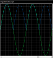
Have a look at this picture:

View attachment 150694

This comes from the attached PDF about AM detection.

Bertus
Yep...time constant is everything. Too long and you get a really nasty-sounding distortion called "diagonal clipping". The optimum RC time constant is a function of both transmitted bandwidth and modulation depth. I've got the formula somewhere in my archives. Stand by!
 

Thread Starter

Dritech

Joined Sep 21, 2011
907
Hi @DickCappels

Yes, I selected a pot instead of a fixed resistor intentionally to vary the ripple.
My issues is that I am not sure what is causing the simulation software to pop the errors/warnings listed in post 20.
Is it someting with the circuit being unstabe (badly designed, incorrect values, etc) ?
 

bertus

Joined Apr 5, 2008
22,926
Hello,

As said a potmeter will adjust the gain.
Connected as a rheostat, it would vary the resistance accross the capacitor and influence the time constant.

Bertus
 

Thread Starter

Dritech

Joined Sep 21, 2011
907
Hi again,

I am using an Absolute Value Circuit (Full-Wave Rectifier) to rectify the signal for better enveloping. Circuit below.
The input is the signal with an offset of Vcc/2, and the rectified output will also have an offset of Vcc/2.
While checking the circuit using a scope, I noticed random clamping at the output signal (VIDEO). What can be causing this? The op-amp used is a rail to rail, so it should not saturate.

upload_2018-7-6_23-39-39.png
 

Thread Starter

Dritech

Joined Sep 21, 2011
907
I believe only the cycle below Vcc/2 (negative cycle) is being clamped, most likely by the diode. I still cannot understand why it i getting clamped.
 

Thread Starter

Dritech

Joined Sep 21, 2011
907
Simulated this on Proteus and got the same responce (screenshot below)
The circuit is that same as shown in this site, with the only difference that the negative terminal is connected to Vcc/2 to have an offset at the output (and different op-amps, but I don't believe this is being caused by the op-amp).

upload_2018-7-7_21-24-25.png
 

kubeek

Joined Sep 20, 2005
5,796
Well,the output of the opamp can only go to 5v if it has rail o rail output. Then the output after the diode can only be about 4.3v max, because the opamp has nowhere to go to make the output 5v.

You can attenuate the signal before the rectifier and amplify it back with the second opamp.
 

bertus

Joined Apr 5, 2008
22,926
Hello,

What is the input voltage?
The page on the given site states an input voltage of ± 3.5 Volts at 5 Volts supply voltage.

Bertus
 

Thread Starter

Dritech

Joined Sep 21, 2011
907
@bertus I am applying a Vcc of 5V and 2.45V peak sine wave with an offset of 2.5V (i.e. max peak is 4.95V).
Is this the circuit to use for rectifying a sine wave (signle supply with Vcc/2 as offset), or should I opt for another circuit?
 

Thread Starter

Dritech

Joined Sep 21, 2011
907
Hi @bertus , but the circuit without the offset makes no sense for my application. Anyway, I tried without the offset (i.e. had to change the supply to dual and remove the input offset) and got the result shown below:

upload_2018-7-8_19-27-47.png
 
Last edited:
Top