 Facebook
 Google
 GitHub
 Linkedin
Hi all,
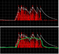
I am using a Peak Detector circuit (circuit shown below, with a 2.2uF cap and a 500k resistor) to envelope a signal.
The output waveform which I am getting on simulation can be seen below (black plot).
Could anyone please suggest any changes which may be implemented to this circuit for me to optain a more enveloped output (i.e. less ripple and sharper falling edge)
Something similar to what I intend to get is also shown below.
Any suggestions would be highly appreciated.
Attachments
-
 8.7 KB Views: 3


