Enhanced Howland Current Source

Thread Starter

Mahabaleshwar Puneeth

Joined May 19, 2016
2
Hi,
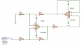
My aim is to get a constant current for different loads from 1K-1M ohm for frequencies ranging from 10K-100KHz.So I'm using Enhanced Howland Current Source as shown in the diagram below. I'm using LMC6482A Op-amp and providing a supply voltage of 2.9V Peak at 10KHz Sine wave.
I'm getting Constant Current as expected but I'm unable to get Sinusoidal waveform at the output.
Anyone is having idea regarding this ???
 

Attachments

#12

Joined Nov 30, 2010
18,224
Not a sine wave? By how much?
What shape?
At all frequencies?

I suspect a slew rate limit above 40KHz.

Is this a real circuit or a simulation?
 

crutschow

Joined Mar 14, 2008
38,484
So what output do you get?
Your op amp has too low a gain-bandwidth (1.5MHz) to get a 100kHz output.
Look for one that has at least a 10MHz GBW.
 

ifixit

Joined Nov 20, 2008
652
Your description is non sequitur. A constant, but alternating current (AC) requirement doesn't make any sense to me.

I suppose you want a current that deviates the same amount independent of the load resistance?

Maybe I'm just too tired.
Ifixit
 

#12

Joined Nov 30, 2010
18,224
Constant current AC does seem to be an abomination, but more than one person has asked for this. Maybe that's what they are teaching in schools today.
 

crutschow

Joined Mar 14, 2008
38,484
So are you objecting to the word "constant" in front of the term "current source" because certainly a current source can be AC since an ideal current source is defined as one that has an infinite output impedance, not unvarying current.
So that means the current is independent of load impedance, not that it never varies.
 

AnalogKid

Joined Aug 1, 2013
12,115
The schematic has no output signal designation.
The part is rated for a max power supply voltage of 16 V, but your schematic shows 24 V.
The part is rated for a min power supply voltage of 3 V, but your post says 2.9 V.
Either way, please restate your question with more attention to the details:
Circuit output point.
Voltage on pin 8.
Voltage on pin 4.
Input AC signal voltage, p-p
Input DC offset voltage, Vdc.

ak
 

Thread Starter

Mahabaleshwar Puneeth

Joined May 19, 2016
2
Thanks for reply guys !! I'm delighted
Actually it's a real circuit using for "Electrical Impedance Tomography".
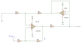
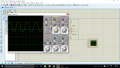
According to Enhanced Howland circuit configuration they have told to maintain the ratio R1/R2 and R3/R4 to get good CMRR but if I'm satisfying that condition I'm not getting the actual sine wave instead i'm getting trapezoidal waveform. But if i'm keeping R4 alone to 100K ohm I'm getting actual sine wave in the output by using the same Opamp.
So I'm bit confused whether it's mandatory to maintain the ratio of resistances??
If i'm not maintaining the ratio whether by any means it will affect the circuit or output.
1. And coming to constant current - I was wrong while posting my question. what I actually meant was for same load but for different frequencies I should get the same value of Peak current.
i.e., For 50K Ohm Load
say for 1Khz input frequency if AC output current is coming around 2mA, then for 100Khz also I should get output of 2mA AC signal.
Coming to Opamp, the slew rate of the Opamp is very low so I will try to use a faster Opamp.
2. Answer for the question asked by #AnalogKid - I have amplified my input signal and reduced Supply voltage and tried to observe the output but no luck, Still I'm getting trapezoid waveform even for 10Khz (which satisfies the Slew Rate condition)
 

Attachments

ScottWang

Joined Aug 23, 2012
7,500
What's your relationship with sachin inamadar?
You both have same IP address and asked the same question and the same circuit, if you are the same person, it is not allowed on this forum, you have to choose which ID want to keep?
 

hp1729

Joined Nov 23, 2015
2,304
Hi,
My aim is to get a constant current for different loads from 1K-1M ohm for frequencies ranging from 10K-100KHz.So I'm using Enhanced Howland Current Source as shown in the diagram below. I'm using LMC6482A Op-amp and providing a supply voltage of 2.9V Peak at 10KHz Sine wave.
I'm getting Constant Current as expected but I'm unable to get Sinusoidal waveform at the output.
Anyone is having idea regarding this ???
Well, I certainly have something to learn here. That doesn't look like a Howland current pump to me, Just an amplifier. What does U1B accomplish?
 

AnalogKid

Joined Aug 1, 2013
12,115
That doesn't look like a Howland current pump to me, Just an amplifier.
An amplifier with 50% positive feedback...?
What does U1B accomplish?
A zero impedance point for the positive feedback. This removes the effect that a variable load impedance has on the effective value of R2, so the bridge stays balanced as the load varies.

A drawback of the original Howland circuit is that 100% of the load current goes through the sense resistor, and that voltage drop decreases the compliance of the current source. The "modified Howland" circuit is one way around this limitation. Another is to make U1B a gain stage.

Overall, the circuit looks more like a Wein oscillator without the reactive elements.

ak
 

AnalogKid

Joined Aug 1, 2013
12,115
Many people are familiar with the standard opamp equations for inverting and non-inverting gain, and a smaller number know about the Howland current pump. Both are derived from the full-blown equation set for a theoretical, differential input, single-ended output opamp. Turns out that the big equations are handy.

A common problem in television, film, and theater production is a decent, hands-free, full-duplex, infinitely expandable intercom. 2 wires are better than three, and 2-wire phones are over 100 years old, so how hard can it be...? Turns out, pretty hard. One problem is that the bidirectional audio must ride on the power, which means that the power supply cannot be a true voltage source; it must have a large enough output impedance that the low power stations can develop audio voltage across it. If you go with something low enough to reduce incidental noise pickup, like 200 ohms, and each station draws 20 mA, and there are 50 stations, then the DC current through the 200 ohm buildout resistance is 1 A, and that takes 200 V. Not good, especially because the output voltage varies with the number of stations connected.

OR - modify a 12 or 15 or 20 V solid state power supply so that it has a non-zero output impedance. One of those long-form opamp equations relates output impedance to the four feedback impedances. An intentionally unbalanced modified Howland circuit can have a 200 ohm output impedance with no (or a very small) physical buildout resistance. This is the basis for the industry-leading intercom system.

ak
 

hp1729

Joined Nov 23, 2015
2,304
An amplifier with 50% positive feedback...?

A zero impedance point for the positive feedback. This removes the effect that a variable load impedance has on the effective value of R2, so the bridge stays balanced as the load varies.

A drawback of the original Howland circuit is that 100% of the load current goes through the sense resistor, and that voltage drop decreases the compliance of the current source. The "modified Howland" circuit is one way around this limitation. Another is to make U1B a gain stage.

Overall, the circuit looks more like a Wein oscillator without the reactive elements.

ak
Thanks for the education. If you wanted to isolate the U1A circuit from the load might you put U1B between the output of U1A and the load? How does the shown configuration accomplish this? If I ground the output of the circuit it will certainly effect operation won't it?
Except for R5 I just see a differential amplifier (inverter) with no gain.

Where might someone use this circuit?
 
Last edited:

AnalogKid

Joined Aug 1, 2013
12,115
Thanks for the education. If you wanted to isolate the U1A circuit from the load might you put U1B between the output of U1A and the load? How does the shown configuration accomplish this?
It doesn't. It isolates feedback resistor R2 from the load, a very different thing. For the circuit to work, the four feedback resistors must appear as a balanced bridge. Without U1B, the thevenin equivalent of R2, R5, and an unknown load resistance does not equal R4.
If I ground the output of the circuit it will certainly effect operation won't it?
Yes, but no opamp can drive a dead short to ground, or function as intended with a dead short in the middle of a feedback path..
Except for R5 I just see a differential amplifier (inverter) with no gain.
I don't. In a single-opamp differential amplifier, R2 would go to the signal ground, no to some form of the output.
Where might someone use this circuit?
A common non-stationary intercom problem is that the number of stations connected to the system can vary greatly, sometimes in the middle of a production. Each station must have an output impedance low enough to let current out onto the icom audio bus but high enough so it doesn't overload the bus. Bus loading increases, and audio volume decreases with each station added. A Howland current pump with the bridge resistors in a resistor network for ratio and thermal tracking can have an effective output impedance of near 1M, and easily put 1 V audio on the bus with only a single 12 V rail.

The circuit has other uses in instrumentation and signal processing.

ak
 

hp1729

Joined Nov 23, 2015
2,304
It doesn't. It isolates feedback resistor R2 from the load, a very different thing. For the circuit to work, the four feedback resistors must appear as a balanced bridge. Without U1B, the thevenin equivalent of R2, R5, and an unknown load resistance does not equal R4.

Yes, but no opamp can drive a dead short to ground, or function as intended with a dead short in the middle of a feedback path..

I don't. In a single-opamp differential amplifier, R2 would go to the signal ground, no to some form of the output.

A common non-stationary intercom problem is that the number of stations connected to the system can vary greatly, sometimes in the middle of a production. Each station must have an output impedance low enough to let current out onto the icom audio bus but high enough so it doesn't overload the bus. Bus loading increases, and audio volume decreases with each station added. A Howland current pump with the bridge resistors in a resistor network for ratio and thermal tracking can have an effective output impedance of near 1M, and easily put 1 V audio on the bus with only a single 12 V rail.

The circuit has other uses in instrumentation and signal processing.

ak
Isolates R2 from the load???
Changes in the output load don't feed through the op amp? R4 doesn't effect the load!!
If we have a bunch of such circuits connected together might all the "R4's" influence each other?

Re: uses
Thank you, again for the education.
 

AnalogKid

Joined Aug 1, 2013
12,115
Isolates R2 from the load???
OK, it isolates the *value* of R2 from the load, as explained in post #14.
Changes in the output load don't feed through the op amp?
Changes in the output load *impedance* don't feed through the opamp. Of course the output voltage does; that's what makes the circuit work.

The same technique is used in gyrators, some active filters, and variations of the phase shift and bubba oscillators.

ak
 

hp1729

Joined Nov 23, 2015
2,304
OK, it isolates the *value* of R2 from the load, as explained in post #14.

Changes in the output load *impedance* don't feed through the opamp. Of course the output voltage does; that's what makes the circuit work.

The same technique is used in gyrators, some active filters, and variations of the phase shift and bubba oscillators.

ak
I finally got it. Thanks.
 
Top