Encoder pulses per mechanical revolution

Thread Starter

kalemaxon89

Joined Oct 12, 2022
389
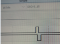
I connected an encoder to a motor and did a full rotation of the rotor with my hand. This is what I see on the oscilloscope:
1730107136737.png
What is the number of pulses per mechanical revolution?
I need it to put it on a simulator.
According to me visually you can tell, and I think it is 1 ... however I ask you how to figure it out and if there is a formula to calculate it

Unfortunately I don't have the datasheet of the encoder and I can't read the model number on the case ... I don't have more informations than what I gave.
Do you think that just from this graph alone you can't tell the pulses for mechanical revolution?
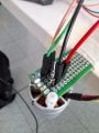
20241014_144324.jpg
20241015_123811.jpg
 
Last edited:

MrChips

Joined Oct 2, 2009
34,765
It would be difficult to count the total number of pulses in one revolution on the oscilloscope.
Try setting the oscilloscope to single capture and rotate the encoder by 1/4 turn. You should be able to capture all the pulses in one sweep.
 

LesJones

Joined Jan 8, 2017
4,511
The trace that that you show inpost #01 looks like a single pulse per revolution. The fact tht the two channels are phase shifted also gives direction information. I have not seen an encoder with a single pulse per revolution. Normaly you see a square wave (50% duty cycle.) on each channel with a 90 degree phase shift between them. When I needed to do this I built a quadrature counter using a pic microcontroller. You need a good way to rotate the encoder EXACTLY one revolution if the encoder gives a large number of pulses per revolution.

Les.
 

crutschow

Joined Mar 14, 2008
38,484
Let the oscilloscope free run while connected to the encoder output, and slowly rotate the encoder one turn while counting the number of times the trace goes up and down.
That will then be the number of pulses per revolution.
 

MaxHeadRoom

Joined Jul 18, 2013
30,628
The trace that that you show inpost #01 looks like a single pulse per revolution. The fact tht the two channels are phase shifted also gives direction information. I have not seen an encoder with a single pulse per revolution.
Les.
The single pulse/rev on an encoder is typically used for a 'Zero-ing' an axis purpose in CNC M/C's etc.
This is as well as the pair of quadrature pules used for positioning, so the typical encoder has three pairs of pulses.
The 'scope trace appears to be of just this single pulse/rev.
BTW, once pulses exceed ~100p/rev, the moiré effect is used in order to read the fine distinction between pulses.
 

Thread Starter

kalemaxon89

Joined Oct 12, 2022
389
It would be difficult to count the total number of pulses in one revolution on the oscilloscope.
Try setting the oscilloscope to single capture and rotate the encoder by 1/4 turn. You should be able to capture all the pulses in one sweep.
The trace that that you show inpost #01 looks like a single pulse per revolution. The fact tht the two channels are phase shifted also gives direction information. I have not seen an encoder with a single pulse per revolution. Normaly you see a square wave (50% duty cycle.) on each channel with a 90 degree phase shift between them. When I needed to do this I built a quadrature counter using a pic microcontroller. You need a good way to rotate the encoder EXACTLY one revolution if the encoder gives a large number of pulses per revolution.

Les.
Let the oscilloscope free run while connected to the encoder output, and slowly rotate the encoder one turn while counting the number of times the trace goes up and down.
That will then be the number of pulses per revolution.
The single pulse/rev on an encoder is typically used for a 'Zero-ing' an axis purpose in CNC M/C's etc.
This is as well as the pair of quadrature pules used for positioning, so the typical encoder has three pairs of pulses.
The 'scope trace appears to be of just this single pulse/rev.
BTW, once pulses exceed ~100p/rev, the moiré effect is used in order to read the fine distinction between pulses.
Some more informations: in the image of the main post, the oscilloscope is in "free running". I am 100% sure that I did a full rotation because the rotor is obviously outside of the motor and I marked with a marker where it starts, so I know (as I turn) where to stop (i.e. 360 degrees complete)

I understand that there are differing opinions on the number of pulses per revolution ?
 
Last edited:

LesJones

Joined Jan 8, 2017
4,511
How many wires are there on the encoder ? I am thinking that as Max suggests in post #5 that the signal you are looking at is the the zeroing signal and there are more wires wit signals from the A & B channels. Can you post some pictures ofpthe encoder and any information you have on the encoder. Teling us what equipment it was removed from may also help. Another suggestion is with the encoder attached to the motor meausre the RPM and also the frequency of the pulses from the encoder.

Les.
 

Thread Starter

kalemaxon89

Joined Oct 12, 2022
389
How many wires are there on the encoder ? I am thinking that as Max suggests in post #5 that the signal you are looking at is the the zeroing signal and there are more wires wit signals from the A & B channels. Can you post some pictures ofpthe encoder and any information you have on the encoder. Teling us what equipment it was removed from may also help. Another suggestion is with the encoder attached to the motor meausre the RPM and also the frequency of the pulses from the encoder.

Les.
images uploaded now in the main post
 

LesJones

Joined Jan 8, 2017
4,511
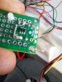
From the pictures that you have posted it looks like the sensor is just a hall effect device. I had assumed that it was an optical encoder. It looks like it is mounted with the hall device close to the and of the motor shaft. I think there will be a small magnet on the end of the motor shaft which will trigger the hall sensor once (Or possibly twice per revolution.). I suspect that the motor was originally in a washing machine. As there a 3 wires coming out from the windings I think it is a three phase motor which will require a controller board to make it work. I have never seen a motor like yours but it looks similar to motors that were fitted to old washing machines. They used a series wound motor and the pulse output (Which was used for closed loop speed control.) that was by a coil mounted close to a magnet on the end of the shaft.
I suspect that your requirement will need more pulses per revolution and it will require two channels with the outputs 90 degrees out off phase with each other.

Les.
 

panic mode

Joined Oct 10, 2011
4,967
there are many types of encoders, one common type is quadrature encoder which has channels A,B and Z
A and B channels are used to measure angle. both would have many pulses per revolution and that is what you are looking for.
Z channel is a marker used for precise referencing and it is a single pulse per revolution.
 

Thread Starter

kalemaxon89

Joined Oct 12, 2022
389
From the pictures that you have posted it looks like the sensor is just a hall effect device. I had assumed that it was an optical encoder. It looks like it is mounted with the hall device close to the and of the motor shaft. I think there will be a small magnet on the end of the motor shaft which will trigger the hall sensor once (Or possibly twice per revolution.). I suspect that the motor was originally in a washing machine. As there a 3 wires coming out from the windings I think it is a three phase motor which will require a controller board to make it work. I have never seen a motor like yours but it looks similar to motors that were fitted to old washing machines. They used a series wound motor and the pulse output (Which was used for closed loop speed control.) that was by a coil mounted close to a magnet on the end of the shaft.
I suspect that your requirement will need more pulses per revolution and it will require two channels with the outputs 90 degrees out off phase with each other.

Les.
the motor I think is the DJI2312
 

MisterBill2

Joined Jan 23, 2018
27,437
I have seen only two photos of the motor, neither of them provide any hint as to what is producing the pulses. I have seen and specified a lot of incremental encoders and the one pulse per revolution is, as MAX has explained, a reference pulse. Normally an incremental encoder also produces two additional pulse trains that are 90 degrees out of phase, so that direction can be determined.
I have seen no other photos except the two that show me nothing except that the motor is white.
Thus my guess is that this is a simple one quadrature pulse pair per revolution installation.
 

Thread Starter

kalemaxon89

Joined Oct 12, 2022
389
I have seen only two photos of the motor, neither of them provide any hint as to what is producing the pulses. I have seen and specified a lot of incremental encoders and the one pulse per revolution is, as MAX has explained, a reference pulse. Normally an incremental encoder also produces two additional pulse trains that are 90 degrees out of phase, so that direction can be determined.
I have seen no other photos except the two that show me nothing except that the motor is white.
Thus my guess is that this is a simple one quadrature pulse pair per revolution installation.
Non capisco una cosa.
What else can I provide to understand the number of pulses per revolution ?
If it is possible, I will gladly do it
 

LesJones

Joined Jan 8, 2017
4,511
You could provide a picture on the end of the motor with the sensor board removed so can see the magnet assembly on the end of the shaft. This is so we can try to understand how it works. The part number of the sensor chip on the board would also be usefull.

Les.
 

MisterBill2

Joined Jan 23, 2018
27,437
If there is anything to be seen in a view of the same end of the motor, but seen at an angle so that what is beneath the circuit board that blocks the view so completely, that might reveal whatever sensor is creating the single pulse pair that we have seen. OR, if that sensor is on the other side of the same PCB, if we see that in another view.

But now, re-examining the photos and captions, it seems that possibly the one photo IS showing what is in the back side of that circuit board. IF that single IC device is the T.I. magnetic encoder, then, first, my apology for not understanding, and second, an explanation is that you only get one pulse per revolution with that sort of encoder, which is quite different from what I am familiar with. That device is not what I recognize as an encoder.
The common encoders that most of us are aware of consist of a shaft with bearings supporting a rotating disc with perforations in a circular pattern,that allow and interrupt a beam of light falling on one or more photo-sensors, to produce a string of pulses per revolution of the disc.
The encoder in this discussion is quite totally different from what we are familiar with, hence our confusion.
 
Last edited:
Top