Eliminating the pop on a PTT electret condenser circuit using a NO switch

sghioto

Joined Dec 31, 2017
8,729
Tried this just now but it didn't have any affect. What is the theory behind it?
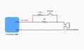
I was in a rush this morning and didn't finish the drawing on the connector. Should have shown a stereo input jack with the 5 volts on the ring and the mic audio on the tip. The theory was to have the mic biased but with a reduced output so the input capacitor would already be charged but this only works if the 5 volts is not switched. (Original Post #15 deleted).
SG
 

sghioto

Joined Dec 31, 2017
8,729
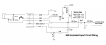
EEE pop eliminator for Lectrosonic.png View attachment 146754
I think you should repost it (with a note about the 5 V connection) because it shows the switched series resistor.ak
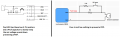
Then the circuit should look like this using the Lectrosonic input.
EDIT: I tested this configuration connected to a signal tracer amp, pop eliminated. R values set bias on the mic element used at 2.5 volts.
SG
View attachment 146738
 
Last edited:

Audioguru

Joined Dec 20, 2007
11,248
The Jfet in the electret mic draws about 0.5mA of current. When you short the resistor or unshort it with the pushbutton then there will be a very loud POP!
 

Thread Starter

greentree

Joined Feb 20, 2018
17
View attachment 146757 View attachment 146754
Then the circuit should look like this using the Lectrosonic input.
EDIT: I tested this configuration connected to a signal tracer amp, pop eliminated. R values set bias on the mic element used at 2.5 volts.
SG
View attachment 146738
Firstly thanks for this idea! Im enjoying trying these out. Just tried this one and the results were the following;
Audio passes whether the switch is pressed or not
There is a slightly delayed pop after releasing the switch

Pin 2 on the Lectrosonics does not need to be connected for the bias to reach and power the mic - it will work with a 2 wire (1 and 3)
 

sghioto

Joined Dec 31, 2017
8,729
Firstly thanks for this idea! Im enjoying trying these out. Just tried this one and the results were the following;
Audio passes whether the switch is pressed or not
There is a slightly delayed pop after releasing the switch

Pin 2 on the Lectrosonics does not need to be connected for the bias to reach and power the mic - it will work with a 2 wire (1 and 3)
Did you connect it exactly as shown in post #23? You need to add the suggested components. You want to power the mic through the switch not from bias voltage on pin #3. Pin #4 should connect to ground to eliminate bias on pin #3.
SG
 

Thread Starter

greentree

Joined Feb 20, 2018
17
I vote for an adjusted version of post #15.

Here is the equivalent input stage of the mic amplifier in post #1:
View attachment 146704
The input is a 300 ohm total resistance to a virtual ground. This is the input series leg of an inverting amplifier. If, for example, the feedback resistor is 30K, then the gain is 100 (+40 dB). If you increase the input resistance to 1,000,300 ohms by adding a 1 M resistor in series with the mic cartridge, then the gain is 0.03 (-30 dB). This is a 70 dB reduction in the audio signal at the output of the internal mic preamp, more then enough to be called "muted". My guess is that something in the 220K - 470K range would give excellent results.

And it's not like we're doing anything new here. Note that the 10K series resistor on the Line In signal does exactly the same thing; it decreases the amplifier gain for that input by increasing the input's source impedance. 10K is 50x 200, so that tells you that the manufacturer thinks the difference is between Line and Mic signal levels is 34 dB.

I have not built and tested this, but it sure looks good on paper.

ak
Thanks for your explanations!
I tried that circuit with a 1M resistor, and while the 1M is a successful 'mute', there is still popping when keying and releasing.

I feel like there needs to be a capacitor somewhere, but I can't figure out where... I have tried putting the switch over a 100uF capacitor both on the negative AND positive leg in separate tests - both had the result of a 'pop' on the push, and a lovely quiet fade on release.
 

Attachments

Thread Starter

greentree

Joined Feb 20, 2018
17
Did you connect it exactly as shown in post #23? You need to add the suggested components. You want to power the mic through the switch not from bias voltage on pin #3. Pin #4 should connect to ground to eliminate bias on pin #3.
SG
Yep copied your diagram exactly with all components. If I link pin 4 to pin 1 there will be no bias at all, and the mic wont work as there would be no DC. Not sure what you mean by powering the mic through the switch - is this something different to what is shown in the diagram?

From what I understand all the components there can be bypassed as 1 and 3 are linked directly to - and +, and the simplest version of this circuit will work with exactly that; 1 to ground and 3 to positive.
 

sghioto

Joined Dec 31, 2017
8,729
Yep copied your diagram exactly with all components. If I link pin 4 to pin 1 there will be no bias at all, and the mic wont work as there would be no DC. Not sure what you mean by powering the mic through the switch - is this something different to what is shown in the diagram?

From what I understand all the components there can be bypassed as 1 and 3 are linked directly to - and +, and the simplest version of this circuit will work with exactly that; 1 to ground and 3 to positive.
I don't think you copied it correctly. The mic gets dc bias from pin #2 via the N.O. switch or push button. Just as it is shown in the schematic. Pin #1 is ground and pin #3 is the mic audio input . You don't need or want any bias on pin #3 which is why you have to connect pin #4 to ground. It becomes a three wire system.
SG
 

sghioto

Joined Dec 31, 2017
8,729
While the voltage on the mic is slowly ramping up and down isn't there some high distortion?
Probably, but the turn on time is quick. By the time you press the switch and say something the mic is fully on. With the components shown the ramp down time was longer. The mic stayed active for about a 1/2 second after the switch was released.
SG
 
Last edited:

Thread Starter

greentree

Joined Feb 20, 2018
17
I don't think you copied it correctly. The mic gets dc bias from pin #2 via the N.O. switch or push button. Just as it is shown in the schematic. Pin #1 is ground and pin #3 is the mic audio input . You don't need or want any bias on pin #3 which is why you have to connect pin #4 to ground. It becomes a three wire system.
SG
Finally had a chance to try all of this and experiment in depth!

I apologise sghioto I missed 4 being connected to 1 in your diagram, I was also under the impression connecting them completely turned bias off in the transmitter.

I have had some success with your suggestion on different levels - I still get a pop when using 4.7k resistor / 47uf capacitor, but increasing to a 100uf capacitor totally eliminates the pop. Only issue with this is there is a long fade out of the audio of 2 to 3 seconds when releasing (which I assume is the large cap discharging). A 4.7uf cap gives a nice quick mute after the switch is released but no matter which resistors I use I always get pops with this size.

By trial and error I got a fairly good combination of 22k resistors with a 22uf cap - this has no pop and a slightly shorter fade out of around 1 second.

Best suggestion so far though! What is the theory to this working?

I don't think its necessary, but where would I put a zener diode in this circuit? I know I have control of the DC level via the wiring, but for safety and out of interest. I've made an attempt at where it would be in the attached diagram.

Thanks again! Awesome to be making this progress
Rob
 

Attachments

Last edited:

Thread Starter

greentree

Joined Feb 20, 2018
17
I tried to sketch a Jfet muting the mic when the pushbutton switch is open then muting the mic when the switch is closed but the resistors sused to turn the Jfet on and off will cause a POP when the switch is used unless the 5V supply is fed to the switch on a 3rd terminal of the plug and jack as I show here:
Had a go at this, but the pop was still present and the audio passed the whole time, regardless of the position of the switch. I fed the bias voltage on a 3rd wire from the transmitter to the switch as instructed.

Thanks for the suggestion anyway
 

Audioguru

Joined Dec 20, 2007
11,248
Why do you want to reduce the voltage powering the Jfet in the electret mic? Most electret mics have a maximum allowed power supply voltage of 10V. When the voltage is reduced then they cause severe distortion on loud sounds. They usually draw 0.5mA and use a 10k series resistor from 9V.

The circuit in post #23 feeds the mic from 5V in series with 10.5K so the voltage at the mic is 2.5V when its current is too low at 2.5V/10.5k= 0.24mA. Or the voltage at the mic is only 1V when its current is only 0.38mA.
You have 44k in series with the 1.1k in the circuit feeding the 5V so your mic gets almost no voltage and almost no current, without the 2V zener which reduces it even more.

I never tried an electret mic when the voltage and current for it are much too low. I assume the output level will be low and distorted.
 

sghioto

Joined Dec 31, 2017
8,729
By trial and error I got a fairly good combination of 22k resistors with a 22uf cap - this has no pop and a slightly shorter fade out of around 1 second.
Best suggestion so far though! What is the theory to this working?

I don't think its necessary, but where would I put a zener diode in this circuit? I know I have control of the DC level via the wiring, but for safety and out of interest. I've made an attempt at where it would be in the attached diagram.
Thanks again! Awesome to be making this progress
Rob
No apology necessary:) I'm just glad you got it working. Trial and error indeed, because of different mic elements. For best results I think you want to choose the resistor values so the voltage across the mic element is between 2 and 3 volts. Once that's set then experiment with different cap values.
The theory is the cap brings the bias supply up "slowly" sort of like a lamp dimmer to prevent the high in-rush current.
You do not need a series zener just use the resistors.
SG
 
Last edited:

MisterBill2

Joined Jan 23, 2018
27,874
Forget the icon that resembles the switch. Its not a push to mute - that diagram is just not well drawn. the switch in the DIAGRAM is NC. when the button is NOT PRESSED the circuit is complete, the audio shorts, and there is no audio. when the button IS PRESSED the short is broken, and an audio signal is passed. Button pressed = able to talk = PTT.

Moving away from this, my question still stands;

Is it possible to create a 'pop free' PTT circuit with an electret condenser and a NO switch?

Thanks
The solution is simple, but maybe not possible. That solution is to separate the PTT function from the microphone function. If you are able to separate those functions then getting rid of the POP is not hard. So let us know if that is possible.
 

Thread Starter

greentree

Joined Feb 20, 2018
17
No apology necessary:) I'm just glad you got it working. Trial and error indeed, because of different mic elements. For best results I think you want to choose the resistor values so the voltage across the mic element is between 2 and 3 volts. Once that's set then experiment with different cap values.
The theory is the cap brings the bias supply up "slowly" sort of like a lamp dimmer to prevent the high in-rush current.
You do not need a series zener just use the resistors.
SG
My understanding grows, I see how the resistors are literally reducing the voltage to the mic, and I see how this voltage is regulated to the circuit through the capacitor by charging up and absorbing the 'burst'

Revisiting each setup Id like to report the following;
Using 4.7k resistors the voltage across the mic is 1.8v, mic works well with this. A 47uf cap in this setup pops and sounds like the audio stumbles, then opens up after a short delay, with a ~2 second fade out. Using a 100uf cap results in a much quieter stumble but with the same initial delay, and a fade out of around 3 seconds.

Using 22k resistors the voltage across the mic is 0.2v - while this is obviously very low it still functions, with the help of a bit more gain.
A 22uf capacitor here is good, it has a very low level pop and a shortish 1 second fade out. Using a 47uf capacitor totally eliminates the pop, but has a ~2 second fade out, and a short opening delay when you press the switch.

The most practical setup for me is the 22k/22uf.

While its not perfect this is a good result, and actually works fine for my setup as its just for comms. This being said I now feel like I'm trying to achieve something that isn't really feasible, at least not in a clean way... are we missing something here?

Thanks again to everyone for their input, this has been a great learning experience
 
Top