Eliminating the pop on a PTT electret condenser circuit using a NO switch

Thread Starter

greentree

Joined Feb 20, 2018
17
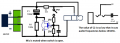
Im looking for a version of this circuit (which eliminates the 'pop' caused by DC voltage powering an electret condenser) that works with a NO switch. The switch in the circuit below is NC.


Is this possible?

Im using a generic walkie talkie covert PTT mic, which I will terminate appropriately into a lectrosonics SMDB transmitter. (circuit diagram on page 11); http://www.lectrosonics.com/europe/phocadownload/SMB_E01_Series_Man.pdf

Thank you in advance!! Rob
 

Dodgydave

Joined Jun 22, 2012
11,302
The capacitor acts as a short circuit until it charges up, are you trying to stop the inrush into the mic or does the "pop" sound come on as soon as the mic is connected to the radio?
 

Thread Starter

greentree

Joined Feb 20, 2018
17
The capacitor acts as a short circuit until it charges up, are you trying to stop the inrush into the mic or does the "pop" sound come on as soon as the mic is connected to the radio?
Im trying to stop the burst of DC hitting the mic each time the PTT switch is keyed.

Im struggling with this as the circuit I have linked as you say works by shorting the mic, but allows the DC to pass the whole time (resulting in no burst). Introducing a NO switch makes this particular method difficult/not possible...

Thanks for your response
 

Audioguru

Joined Dec 20, 2007
11,248
What is the problem? The switch is shown as a NO, not as a NC. The capacitor is charged by the resistor and the mic works normally when the CO switch is open. Then when the switch is closed the capacitor shorts the AC signal from the mic but leaves the DC unchanged. But only if the capacitor is fairly new and has no leakage current. An old capacitor will become unformed and has current until it is reformed. or use a huge and expensive non-polarized film capacitor.
Also if there are loud sounds a POP is produced if the switch is closed during a peak in the sound level. Then you need to ramp the gain down.
 

Thread Starter

greentree

Joined Feb 20, 2018
17
What is the problem? The switch is shown as a NO, not as a NC. The capacitor is charged by the resistor and the mic works normally when the CO switch is open. Then when the switch is closed the capacitor shorts the AC signal from the mic but leaves the DC unchanged. But only if the capacitor is fairly new and has no leakage current. An old capacitor will become unformed and has current until it is reformed. or use a huge and expensive non-polarized film capacitor.
Also if there are loud sounds a POP is produced if the switch is closed during a peak in the sound level. Then you need to ramp the gain down.
The switch in that diagram does not have the correct symbol, that circuit only works with a NC switch. It uses a short to mute when closed.

I need a version of this circuit that works with a NO switch. To put it simply, I want to achieve a pop free circuit with a PTT (NO switch) and an electret condenser. No audio when switch is open, and audio when switch is engaged, without a pop.
 

Audioguru

Joined Dec 20, 2007
11,248
PTT means Press To Talk. Therefore your drawing is backwards, and shows Press To Mute.
Use a changeover switch instead that has both NO and NC.
 

Thread Starter

greentree

Joined Feb 20, 2018
17
PTT means Press To Talk. Therefore your drawing is backwards, and shows Press To Mute.
Use a changeover switch instead that has both NO and NC.
Forget the icon that resembles the switch. Its not a push to mute - that diagram is just not well drawn. the switch in the DIAGRAM is NC. when the button is NOT PRESSED the circuit is complete, the audio shorts, and there is no audio. when the button IS PRESSED the short is broken, and an audio signal is passed. Button pressed = able to talk = PTT.

Moving away from this, my question still stands;

Is it possible to create a 'pop free' PTT circuit with an electret condenser and a NO switch?

Thanks
 

Audioguru

Joined Dec 20, 2007
11,248
Try using a Jfet to connect the capacitor to ground. When the gate has no bias voltage (a resistor to ground at its gate) then the Jfet is turned on and connects the capacitor to ground. When the switch provides negative bias to the gate of the Jfet then it turns off.
 

Thread Starter

greentree

Joined Feb 20, 2018
17
Try using a Jfet to connect the capacitor to ground. When the gate has no bias voltage (a resistor to ground at its gate) then the Jfet is turned on and connects the capacitor to ground. When the switch provides negative bias to the gate of the Jfet then it turns off.
Ok cool thanks for this suggestion - Im new to Jfets - Ive never used them before. Ive read the article here on AAC and gather an applied voltage will trigger the Jfet 'switch' into 'off', muting the circuit. Does this use the DC to trigger the Jfet? Would you mind drawing a circuit diagram for me so I can understand a bit better please? Im not sure if you mean in place of the switch/resistor, or in series.

Thanks!
 

Audioguru

Joined Dec 20, 2007
11,248
Can you provide a link or model number of the mic you are using? Are you sure it's a condenser type?
SG
It is not a condenser type that needs a 48V supply. Instead it is an electret type that has the 48V built into its electret material and it has an internal Jfet common source to match its extremely high impedance to a few thousand ohms.
 

Audioguru

Joined Dec 20, 2007
11,248
I tried to sketch a Jfet muting the mic when the pushbutton switch is open then muting the mic when the switch is closed but the resistors sused to turn the Jfet on and off will cause a POP when the switch is used unless the 5V supply is fed to the switch on a 3rd terminal of the plug and jack as I show here:
 

Attachments

sghioto

Joined Dec 31, 2017
5,388
It is not a condenser type that needs a 48V supply. Instead it is an electret type that has the 48V built into its electret material and it has an internal Jfet common source to match its extremely high impedance to a few thousand ohms.
Yeah an electret condenser mic that's what I was talking about. But the question was for the OP.:)
SG
 

Thread Starter

greentree

Joined Feb 20, 2018
17
I tried to sketch a Jfet muting the mic when the pushbutton switch is open then muting the mic when the switch is closed but the resistors sused to turn the Jfet on and off will cause a POP when the switch is used unless the 5V supply is fed to the switch on a 3rd terminal of the plug and jack as I show here:
Thanks for the diagram, I will order some Jfet's and play around with this. Just double checking this is 'muted' when switch is open (not pressed) and audio passes when the switch is closed (pressed). Slightly confused by the first part of your post.

Is there any particular Jfet I should get? voltage bias in this circuit is 2v if that affects this decision

The bias is supplied via the + (same as audio) in my setup, so im not sure If your suggestion to feed it via a separate pin is possible

Thanks again for the help everyone this is all interesting stuff
 

AnalogKid

Joined Aug 1, 2013
11,039
In the radio, the mic input stage is an inverting opamp, so it presents a virtual ground to the input connector through a series gain-setting resistor. If you increase that resistance by putting another large resistor in series with it, the stage gain goes down. Instead of 22K, try 1M or higher.

I like this approach because it doesn't alter the DC relationship between the mic and the input.

ak
 

Audioguru

Joined Dec 20, 2007
11,248
The sketch that switches resistor values has the 5V supply shorting the audio output of the mic all the time. If the signal is taken from the mic instead of from the +5V then the signal level will be a little higher with distortion with the higher resistor value. It will not mute the mic unless the voltage feeding the mic is 0V which will cause an extremely loud POP!

I have used many N-channel Jfets but never a P-channel. I looked at the guide at Digikey and entered "a P-channel that turns on well with 0V gate bias and turns off well with 4V gate bias" and the guide selected the wrong kind (an N-channel) that is not in stock.

Why can't you use a NO switch to simply not pass the signal when open but pass the signal when closed?
 

AnalogKid

Joined Aug 1, 2013
11,039
I vote for an adjusted version of post #15.

Here is the equivalent input stage of the mic amplifier in post #1:
upload_2018-2-22_13-46-17.png
The input is a 300 ohm total resistance to a virtual ground. This is the input series leg of an inverting amplifier. If, for example, the feedback resistor is 30K, then the gain is 100 (+40 dB). If you increase the input resistance to 1,000,300 ohms by adding a 1 M resistor in series with the mic cartridge, then the gain is 0.03 (-30 dB). This is a 70 dB reduction in the audio signal at the output of the internal mic preamp, more then enough to be called "muted". My guess is that something in the 220K - 470K range would give excellent results.

And it's not like we're doing anything new here. Note that the 10K series resistor on the Line In signal does exactly the same thing; it decreases the amplifier gain for that input by increasing the input's source impedance. 10K is 50x 200, so that tells you that the manufacturer thinks the difference is between Line and Mic signal levels is 34 dB.

I have not built and tested this, but it sure looks good on paper.

ak
 
Last edited:
Top