Facebook
 Google
 GitHub
 Linkedin

Thanks for any help with the following two questions
TWO RELATED QUESTIONS , Please directly answer one of the two directly.
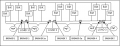
The goal is to disable the entire circuit if the battery failure transfers load above a preset limit defined by the breakers.
Using Only these Assumptions as Given:
DC circuit, positive side only shown on schematic, all negatives connected. Breakers on positive side only
Assume zero resistance
Fixed voltage
All batteries supply all loads evenly
All breakers normally closed
Make no other assumptions about the circuit...thanks!
Scenario I: Given: Only Load 1 is active drawing 14 amps
So: 1 amp draw per battery
Logically the load at "Breaker 4" is 2 amps, Breaker 3 is 11 amps, Breaker 2 is 8 amps, and Breaker 1 is 3 amps
QUESTION ONE: BASED on ONLY the Assumptions, *** What is the load at Breaker 4 and Breaker 3? ***IS THIS Logic CORRECT IN A DC circuit?
If so:
Scenario 2: If on Leg E the 2 batteries deliver zero power for any reason, then the 2 amps is distributed to the other batteries.
So: Measured amperage at Breakers 1, 2, 3, and 4 increase
What I want to do is first break the entire circuit to Load 1 at Breakers 1 and 2 if the demand exceeds a certain level (Say 10 amps) on Leg A and B if a enough battery failures occur.
If ALL loads are Active from Loads 1, 2 and 3, This will have a transferring cascading effect on all the other breakers disabling the entire circuit. Exactly what I want.
So: If all breakers are rated 10 amps, when enough batteries fail to produce an increase in load exceeding the wiring or battery output limits (say 12) Enough failure will trip all breakers.
QUESTION II ** Is my reasoning correct here? **
I simply do not know the behavior of the load on the legs in a DC circuit.