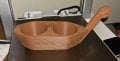
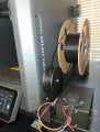
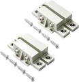
As much as I love my new printer, changing the filament is pretty easy. Unfortunately, every time I change the filament I have problems with tangles in the spool. So I built an alarm circuit when the tangle causes the pulley to be pulled off the base with that is attached with magnets It sounds an alarm so I can pause the printer and untangle the filament. Unfortunately, it may do it more than once, so I just have to live with it. The ELEGOO Centauri Carbon 3D Printer printer allows me to pause the print long enough for me to go fix the problem and complete the print. Until I got this online, I lost more than one print in the process. I used 4/40 x ¼“ screws to attach the various pieces of the table mount together. The holes in the print are the tap size for the screws. The soft plastic is easily inserted with these screws. Most of the magnets I used are variations on 5/8” or 5/16” diameter magnets. I used window sensors similar to these I can no longer get those parts so the holes may not be the right place. I've had them for over five years, go figure. The magnet side of the sensor is mounted in the pulley along with two magnets to firmly attach it to the table mount, Which has the contacts used by the alarm circuit. When the pulley is dragged off the table mount, it opens the circuit and the alarm goes off.
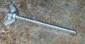
There is a minor Design flaw w/ pulley base with magnets STL in that the retaining screws for the magnetic door sensor overlaps with a magnet. I cheated and used a drop of super glue to retain the top to the pulley base. The pulley comes in two parts The top half slides over the bottom half, I used super glue to hold them together. A #6/32 screw that had been cut down to full use as the pulley shaft. I used a #6/32 countersunk screw with a #6/32 wing nut as shown, to attach the table mount to the table underneath. I used superglue to attach the wingnut to a #6/32 countersunk screw.and cut it down as needed. I keep a stock of screws two inches long. I cut them down when I need to.
I built the circuit on a small protoboard and mounted it on the base of the box using two small retainers I made to hold the protoboard in the box stationary.
And here is the schematic and layout:
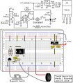
I used an existing voltage, 17 to 24VDC, that I used for my filament warmer to power the total circuit. I used a 15V regulator to get it down to where a CMOS 555 can handle it. Why CMOS? This kept the regulator running cool at 15V a CMOS 555 has pretty decent specs.
The sides.STL files have something I call square strain relief. You glue the wires into this square strain relief, and put them in the side that has the gap. This is the sensor leads and the power supply leads. When you slide these wires down the gap in one of the sides You then use the gap filler to plug the gap in side right and plug that hole.
There is a minor Design flaw w/ pulley base with magnets STL in that the retaining screws for the magnetic door sensor overlaps with a magnet. I cheated and used a drop of super glue to retain the top to the pulley base. The pulley comes in two parts The top half slides over the bottom half, I used super glue to hold them together. A #6/32 screw that had been cut down to full use as the pulley shaft. I used a #6/32 countersunk screw with a #6/32 wing nut as shown, to attach the table mount to the table underneath. I used superglue to attach the wingnut to a #6/32 countersunk screw.and cut it down as needed. I keep a stock of screws two inches long. I cut them down when I need to.
I built the circuit on a small protoboard and mounted it on the base of the box using two small retainers I made to hold the protoboard in the box stationary.
And here is the schematic and layout:
I used an existing voltage, 17 to 24VDC, that I used for my filament warmer to power the total circuit. I used a 15V regulator to get it down to where a CMOS 555 can handle it. Why CMOS? This kept the regulator running cool at 15V a CMOS 555 has pretty decent specs.
The sides.STL files have something I call square strain relief. You glue the wires into this square strain relief, and put them in the side that has the gap. This is the sensor leads and the power supply leads. When you slide these wires down the gap in one of the sides You then use the gap filler to plug the gap in side right and plug that hole.
Attachments
-
51.7 KB Views: 0
-
18.2 KB Views: 0
Last edited: