Ok..... I understood! Should I show this symbol to someone else who knows this symbols? If yes I will keep it in mind, if no I will keep it in mind too
You mean that one from all this switches (let's take one of them) is the same switch that is connected in all the 4 places where is that symbol? If yes then ok XD
You mean that one from all this switches (let's take one of them) is the same switch that is connected in all the 4 places where is that symbol? If yes then ok XD
Yes, the top one works well for your application. It is four switches activated by one button. Each switch has three pins (twelve total) with six pins on each row. The first three pins make a switch (middle pin is the common and the one closest to the touch point is R. As you push, the center pin is connected to the far pin (of a group of three). That far pin in each group of three is the T.
Yes, the top one works well for your application. It is four switches activated by one button. Each switch has three pins (twelve total) with six pins on each row. The first three pins make a switch (middle pin is the common and the one closest to the touch point is R. As you push, the center pin is connected to the far pin (of a group of three). That far pin in each group of three is the T.
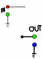
Guys thanks that you explained me all the symbols (almost) but I want to ask another question! What is the difference between the following connections?
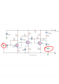
I cannot understand what is the difference between the "wired junction" connection and other that I don't know the name? I tried to make one of the class AB audio amplifiers but this connections get me confused! I cannot understand why the circuit didn't work!!!
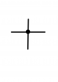
The typical convention is if wires cross without a connection dot, there is no connection. That avoids the need for the "humps" in the marked up picture. When a wire intersects, but does not cross (e.g. a "T"), the connection dot is optional. Without the dot, a connection is still assumed.
Well drawn schematics will be consistent in the way they use or don't use dots. You should never see a schematic like the marked up one...
See this link! Maybe you will understand what I mean. Why this man made the typical connection or how its called like "T"? The components around this connection is not connected by the "T"? And the connection near the GND? The pin of audio IN where is connected? To the ground or to the pin of a PNP transistor?
 Facebook
 Google
 GitHub
 Linkedin