Facebook
 Google
 GitHub
 Linkedin
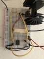
My current project is an electronic load. To test it before I design a pcb, I decided to build a very simple prototype. The circuit is your common load circuit thats all over the internet with an op amp, mosfet, and sense resistor.

The op amp is a tle2141 and the mosfet is ixth64n10L2. However after running a test, I got a weird voltage, definitely not the expected 5v at the inverting input of op amp. I wanna say it was around .6v. Now I thought this was weird so I built another circuit using the common LM358 and IRFZ44n. I used this because many loads have been successfully built with these components. This time the inverting input was .56v. My understanding of the circuit is that the op amp will drive its output to whatever value it takes the get its inputs to the same voltage. This means that there should be 5v at the resistor and according to ohms law 500ma flowing through the circuit.
I went into LTSPICE and simulated that exact circuit, only to get 2.5mv.

Does anyone have any idea of whats going on?
The op amp is a tle2141 and the mosfet is ixth64n10L2. However after running a test, I got a weird voltage, definitely not the expected 5v at the inverting input of op amp. I wanna say it was around .6v. Now I thought this was weird so I built another circuit using the common LM358 and IRFZ44n. I used this because many loads have been successfully built with these components. This time the inverting input was .56v. My understanding of the circuit is that the op amp will drive its output to whatever value it takes the get its inputs to the same voltage. This means that there should be 5v at the resistor and according to ohms law 500ma flowing through the circuit.
I went into LTSPICE and simulated that exact circuit, only to get 2.5mv.
Does anyone have any idea of whats going on?