Electromagnetic field sensing circuit

Thread Starter

FPGA_expert2015

Joined Mar 30, 2015
12
Hi All ,

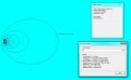
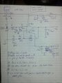
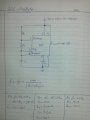
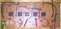
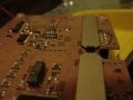
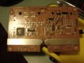
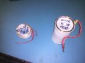
I need professional advice on a problem I am trying to solve . I am trying to sense electromagnetic field created by an iron-core coil from a distance of 12-feet. The Transmitter coil is 6-inches in length , #30 AWG wire is winded on it up the thickness of about 0.5 inches ( I don’t remember the number of turns ), its total impedance is 240ohms. See pic attached . I have a derive circuit in which a 555 is generating 25Hz of square wave its output is amplified by a LM1875 which is supplied +/- 25V to output amplified signal . The signal is fed into the winding and the other end is just grounded .

My Receive coil is a small with total impedance of 2.4Kohm because #44 AWG wire in winded on it , this coil is air core .

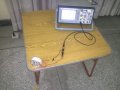
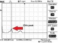
When I do testing I just connect both ends of Rx coil to the scope , I get very strong signals when Rx coil is line with either end of Tx coil because iron core amplifies the Magnetic field on both ends of Tx coil . I did some FEMM simulation and it shows that magnetic field should extend outwards beyond 14-feet . But I don’t see any signal or the FFT function of the scope doesn’t show any spike at 25Hz beyond 1-feet , although when Rx coil is inline with the end of TX coil I do see signal embedded in the noise . But my requirement is that Rx coil should detect 25Hz when place 12-feet away in length-wise parallel to the Tx coil .

Thanks in advance for all the valuable comments and replies .
 

Attachments

Papabravo

Joined Feb 24, 2006
21,159
Excuse me but some of those numbers on the simulation look very strange.
I seriously doubt that the real power is 8028.8 Watts

I understand what you want, but you may not be able to get there with that setup.
 

wayneh

Joined Sep 9, 2010
17,496
I get 100mA current in the coil, ignoring its inductance. Where does the 2A come from? And yeah, 8kW is not happening. It would vaporize in a blinding flash.
 

BR-549

Joined Sep 22, 2013
4,928
This is not what you want, but it might help you understand.

Put aside your two coils for the time being.

Mount transmitter half way up an external wall.

Start with a one conductor loop around the external walls of your work area/room. I have not seen your generator circuit. Limit current if necessary.

Fashion a 1 or 2 foot loop in the center of the room.

Attach twisted oscilloscope leads to feed-point of receiving loop.

Orientate the receiving loop co-planar to the transmitting loop.

Now you can experiment with the amp-turns of both loops.

You can change the size of the loops. Various core media.

Also experiment with changing the small loops location inside the large loop. This is always interesting.

With your current frequency.......if you have florescent lighting....you might need a low pass filter on RX loop.
 

Thread Starter

FPGA_expert2015

Joined Mar 30, 2015
12
This is not what you want, but it might help you understand.

Put aside your two coils for the time being.

Mount transmitter half way up an external wall.

Start with a one conductor loop around the external walls of your work area/room. I have not seen your generator circuit. Limit current if necessary.

Fashion a 1 or 2 foot loop in the center of the room.

Attach twisted oscilloscope leads to feed-point of receiving loop.

Orientate the receiving loop co-planar to the transmitting loop.

Now you can experiment with the amp-turns of both loops.

You can change the size of the loops. Various core media.

Also experiment with changing the small loops location inside the large loop. This is always interesting.

With your current frequency.......if you have florescent lighting....you might need a low pass filter on RX loop.

Hi ,

Do you have a document that explains that , you mean i mount a #44 wire all across the exterior of my room and test a Rx loop inside my room , but that is not what i trying to achieve .
 

Thread Starter

FPGA_expert2015

Joined Mar 30, 2015
12
Hi ALL, i am not trying to light a bulb or charge something 8 feet away ,i just need to sense 25Hz from a distance of 8 to 12 feet away , i dont care even if its modulated RF i.e pulses of 25Hz but during 40ms of high its 4 or 5 Mhz pulses and when its low for another 40ms its silent .

How do i do that , any leads ???
 

wayneh

Joined Sep 9, 2010
17,496
You could turn a crystal oscillator on and off at 25Hz, and it will act as a short range radio transmitter. Or just buy yourself an RF remote control.
 

BR-549

Joined Sep 22, 2013
4,928
I believe that if you want true coil to coil(near field) link.......you will have to increase coil radius and power at transmitter.
If an rf link will do......attach 1 or 2 foot wire to coils.
I believe the near field will decrease at a much faster rate than the rf field.
 

Thread Starter

FPGA_expert2015

Joined Mar 30, 2015
12
I am going to make a butterworth active filter with a gain of 4 and connect Rx coil to it and see will this improve its reception , the Rx coil does pick up 25Hz when facing Tx coil end at a distance of 8-feet , but when i put Tx coil upright the spike of the FFT trace dies down . see pick attached
 

Attachments

BR-549

Joined Sep 22, 2013
4,928
FPGA,

I believe you have mis-understood the concept.

Or perhaps I have.

You should have mentioned the 4-6 mhz signal in first post.

You are not trying to detect the 25 hz signal.

You are trying to detect the 4-6 mhz signal.

Get rid of iron cores.

The length of the 4-6 mhz signal.......will give you the 25 hz signal.

wayneh has the right idea.

Key the 4-6 mhz oscillator on and off at any rate you want.

Add a short length of wire to your tank circuits.

Review rf circuitry and modulation techniques.
 

Thread Starter

FPGA_expert2015

Joined Mar 30, 2015
12
Here are the results of testing Rx coil with a 8-order Sallen-key active filter , on the last stage of the circuit i ran out of accurate values of the capacitors or the sales guy from where i bought it didnt had 5% capacitor for those values , bottom line is it did cleaned the signal , but time domain trace dosent show anything except for over-riding noise, only when i plot FFT i see a nice spike at 25Hz at a distance of 6ft . see pics attached
 

Attachments

Thread Starter

FPGA_expert2015

Joined Mar 30, 2015
12
Actually my approach is wrong to detect magnetic field at a distance of 12ft or more a Hall-effect sensor is used and to channel field into sensor metal strips are used to direct field into its sense axis , they work at low voltage and also Tx coil doesn't have to running on very high voltage and current , see pics attached
 

Attachments

Top