Electro magnet project

Thread Starter

JCOX

Joined Nov 29, 2011
136
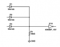
So here is what I need to do, because I don't want to change the 4025 inputs again it will be easier to just run the output through 2 inverters, I also changed the 10 ohm resistors to 20 ohms. By changing the resistors is it supposed to remove those spikes that i see on the scope?


praondevou

Joined Jul 9, 2011
2,942
So here is what I need to do, because I don't want to change the 4025 inputs again it will be easier to just run the output through 2 inverters, I also changed the 10 ohm resistors to 20 ohms. By changing the resistors is it supposed to remove those spikes that i see on the scope?
Ok.

Yes, since we don't know the reason for the IC failure, increasing those resistors can help to attenuate any spikes/oscillations.
 

Thread Starter

JCOX

Joined Nov 29, 2011
136
very little progress last night, I was able to check the output of the 4025 without it being attached to the FETs. it still did not show a pulse. I checked the resistance in all the MOSFET's in the fashion as you explained and they all had resistance.
 

praondevou

Joined Jul 9, 2011
2,942
very little progress last night, I was able to check the output of the 4025 without it being attached to the FETs. it still did not show a pulse. I checked the resistance in all the MOSFET's in the fashion as you explained and they all had resistance.
Ok, so the 4025 gate is dead. There are two spare gates in this package. Take one of them and use it instead.
 

Thread Starter

JCOX

Joined Nov 29, 2011
136
yes I rewired it to use 3,4 & 5 inputs but still had constant 12v output from pin 6. I'm guessing the other gate is the same way. should I wire it up and see?


and my jumper wire that I was using to keep 12v to the FETs fell off and T7/T8 got hot really quick. I quickly turned it off and allowed it to cool down. then tested the resistance through them again to to ensure nothing bad happened, there's still resistance.
so did I hurt the FETs?

maybe my next project needs to be a current limiting power supply.
 

praondevou

Joined Jul 9, 2011
2,942
yes I rewired it to use 3,4 & 5 inputs but still had constant 12v output from pin 6. I'm guessing the other gate is the same way. should I wire it up and see?
Wow, that's strange, why would an unused gate be affected? There must have been transients on the power supply for that chip then... Does it also have a 100n cap over it's power supply pins?
If this chip is completely dead you don't have a spare one, right?

Do you have 3x 1N4148 diodes and a resistor between 4k7 and 47k left then?

and my jumper wire that I was using to keep 12v to the FETs fell off and T7/T8 got hot really quick. I quickly turned it off and allowed it to cool down. then tested the resistance through them again to to ensure nothing bad happened, there's still resistance.
so did I hurt the FETs?

maybe my next project needs to be a current limiting power supply.
:D They should be ok, when MOSFETs are defective they usually are short circuited between drain and source or gate.
 

praondevou

Joined Jul 9, 2011
2,942
I would probably start over and use only resistors as load, once it's working again. Then connect one coil, measure possible voltage transients (depends on the layout) on the power supply pins of the 4017, 4025 and 4049.

Then test connect the next coil do the same measurements etc.

Troubleshooting over the net is not so easy :(
 

Thread Starter

JCOX

Joined Nov 29, 2011
136
Do you have 3x 1N4148 diodes and a resistor between 4k7 and 47k left then?
I don't understand the 4k7 but I do have the diodes and tons of resistors ( bought the variety pack)

I don't have another 4025 though

oh and yes the caps are there too.
 

praondevou

Joined Jul 9, 2011
2,942
I don't understand the 4k7 but I do have the diodes and tons of resistors ( bought the variety pack)

I don't have another 4025 though

oh and yes the caps are there too.
Ok, I would check if the last 4025 gate is also dead, if it is then "make" one like this:


Attachments

Thread Starter

JCOX

Joined Nov 29, 2011
136
checked the third onr and pretty much the same thing, except this one had a hint of a pulse it moved from 12v to11.8v.

you know..... (try not to roll your eyes) I do have another 4025 from the other one I built. put it in and it works again.
 

thatoneguy

Joined Feb 19, 2009
6,359
It appears to be staying 1 or two diode drops away from zero, I can't see the divisions on the screen, so I'm kind of guessing from the ticks down the left side.

Where are these measurements taken? At the gates, or the output of the logic?
 

Thread Starter

JCOX

Joined Nov 29, 2011
136
they are taken from the drain with the ground probe set to T7/T8 drain . when I measure from the gates they look right (0-12v)

the division is set to 1 second, the display screen shows 1 second worth of informaition.
 

praondevou

Joined Jul 9, 2011
2,942
Actually it goes back to zero but the signal is being lifted to a higher level...

Test it with resistors instead of coils as you did before.

Is any of the transistors getting hot? (or warmer than the others)
 

Thread Starter

JCOX

Joined Nov 29, 2011
136
here it is with 4.7k resistors on it instead of the coils.


does this mean there's something wrong with the coils?
 

praondevou

Joined Jul 9, 2011
2,942
here it is with 4.7k resistors on it instead of the coils.


does this mean there's something wrong with the coils?
Hmm. What could there be wrong with coils? The main difference with or without coils is the amount of current flowing through the FETs.
I can't remember it, did you measure this signal over the coils when it was working?

Try to test it without the coils but e.g. 20Ohms power resistors instead of the coils.
 
Top