Electro magnet project

thatoneguy

Joined Feb 19, 2009
6,359
table saw and an old blade. :)
+ Lots of skill to get the cutout for the fan so symmetrical with the nice curve. My hat is off to you.

--ETA: I'd suggest Black "capscrews" that use an allen wrench for all externally visible fasteners. It makes things look a lot cleaner, and you can get feet that fit right over them so the box doesn't scratch anything.
 

Thread Starter

JCOX

Joined Nov 29, 2011
136
+ Lots of skill to get the cutout for the fan so symmetrical with the nice curve. My hat is off to you.

--ETA: I'd suggest Black "capscrews" that use an allen wrench for all externally visible fasteners. It makes things look a lot cleaner, and you can get feet that fit right over them so the box doesn't scratch anything.
The hole was done with a drill press and a dremal.

Excellent idea for the fasteners, I just used what was available. Do you have a link as to where I can find them?

Good job !!!!!!
Thanks


Now for some bad news,

I was playing with it last night, and I think that something happened to the circuit after I switched from normal mode to random mode. the magnet stopped spinning just bounced back and forth, I switched it back to normal mode and it continued to do the same thing. I still have the scope so I hooked it up with the ground probe to the gates of T7/T8 and all the others to each other gate.


It's no longer flipping to -12v. However when I change the 1M pot the pulses speed up and slow down.

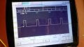
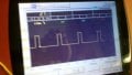
Here is the output of the 555


Note that it is at 50 us and the gates are at 100 ms. What do you think the possible problems could be?
 

praondevou

Joined Jul 9, 2011
2,942
I still have the scope so I hooked it up with the ground probe to the gates of T7/T8 and all the others to each other gate.
The load was the coils I assume?

Don't connect the ground probe to gates. Either to Gnd or to the drains of T7/T8.
If possible post a scope picture of

- the signals over the coils (ground probe connected to drains T7/T8
- the gate signals identifying each of them (ground probe connected to 0V)

The 555 output looks ok. It gives out very short pulses because of the way it is configured. You can see that it works because the counter 4017 is still functional.
 

Thread Starter

JCOX

Joined Nov 29, 2011
136
I'm sorry that's what I meant, I connected all of the probes to the "drains" the ground was to T7/T8 and that's what the scope is showing, and there was no load at the time. Because it's not flipping, I'm assuming that it's because of either the 4025 or the 4049. Is there a way to test those?
 

praondevou

Joined Jul 9, 2011
2,942
I'm sorry that's what I meant, I connected all of the probes to the "drains" the ground was to T7/T8 and that's what the scope is showing, and there was no load at the time. Because it's not flipping, I'm assuming that it's because of either the 4025 or the 4049. Is there a way to test those?
yes, measure between ground and the outputs of the 4025 and 4049 and post the results.
 

Thread Starter

JCOX

Joined Nov 29, 2011
136
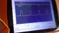
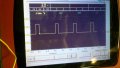
Here is the 4025, it is constant at 12.3 volts that's at 50us and I moved it down to 20 seconds as well and it doesn't move.


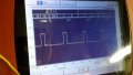
And here's each of the 3 outputs of the 4049 @ 2 ms, they seem pretty much the same.


What do you make of it?
 

praondevou

Joined Jul 9, 2011
2,942
Ok, the 4049 outputs are obviously ok.
I need the signals from the gates of T2, T4, T6 (n-channel MOSFETs). These come directly from the 4017.

Also the 3 inputs of the 4025 gate whose inexistant output signal you just posted. (probably ok)
With all inputs 0 the output has to be 1, with at least one input 1 the output should go low, if it doesn't the output is defective. If that's the case, open the resistor that is connected to the 4025s output and connect it to +12V.

Then check the 4025s output again.
 

thatoneguy

Joined Feb 19, 2009
6,359
The hole was done with a drill press and a dremal.

Excellent idea for the fasteners, I just used what was available. Do you have a link as to where I can find them?

Thanks
I get them personally from a local hardware store like Ace Hardware, any of the "old style" hardware stores that have a few walls of drawers to choose fasteners from. They also sell the feet that go over the screws.
 

Thread Starter

JCOX

Joined Nov 29, 2011
136
ok. im uploading.the pics now. all the image look the same with minor differences to the voltage.

If that's the case, open the resistor that is connected to the 4025s output and connect it to +12V.

Then check the 4025s output again.
if I understand correctly. im removing one end of the the 10 ohm resistor and then supplying 12v to the output (pin#9) of the 4025? is that correct? is that some sort of reset?
 

praondevou

Joined Jul 9, 2011
2,942
then supplying 12v to the output (pin#9) of the 4025? is that correct? is that some sort of reset?
NOOOO, please don't !:)

The output remains open and you measure with the scope if there is really no pulse while there should be (due to the inputs changing between all zero or one at HIGH level)

The end of the resistor you opened you tie to 12V for this test, just to let the MOSFETs gates not floating.
 

Thread Starter

JCOX

Joined Nov 29, 2011
136
NOOOO, please don't !:)

The output remains open and you measure with the scope if there is really no pulse while there should be (due to the inputs changing between all zero or one at HIGH level)

The end of the resistor you opened you tie to 12V for this test, just to let the MOSFETs gates not floating.
got it. makes sense...does it matter what side of the resistor I remove? can I supply the full 13v to the FET? or do I HAVE to go through a resistor? its easy to remove the connection between the circuit boards than it would be to remove the resistor..
 
Last edited:

praondevou

Joined Jul 9, 2011
2,942
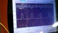
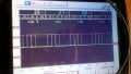
here are the 4017 outputs 1,0 and 2 (T4, T2 & T6) respectively.
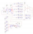
Is the 4025 connected to the 4017 as per post 230?

If so the 4025s inputs are connected to pins 3, 2 and 4, which you just measured. The 4025 gate is apparently damaged.

We need to confirm that before continuing.

Can you measure the 3 inputs (pin 1, 2 and 8) and the output (pin 9) of that 4025 gate at the same time?
 

Thread Starter

JCOX

Joined Nov 29, 2011
136
here it is pin 1,2 and 8 and the red is the output. not switching at all. which means that it is s in fact the 4025.

and I realized that I didn't answer your question about how I have the inputs wired... I did change everything around from the 4017 to accommodate the 4025 instead of the 4075. so the inputs are connected to 0, 1 and 2 of the 4017.


do you still need me to remove the resistor from the output and test it alone?
 

Attachments

praondevou

Joined Jul 9, 2011
2,942
do you still need me to remove the resistor from the output and test it alone?
You could do that, just to make sure, you only need to measur ethe output for that, the inputs are ok as we have seen.

If it then really doesn't do anything, you will need to use another 4025 gate.

I will refer to post #230 from now on.

You can connect two of the spare 4049 inverters in series between the 4025 and R17

OR

connect the inputs of the 4025 to Q3 Q4 and Q5 of the 4017 and then use only 1 spare 4049 inverter and connect it between the 4025 and R17.

Test the circuit with R17 open, i.e. check the pulses out of the 4049.

The 4049 is a buffer , it has a higher output current rating.

Check T7 and T8 for short circuit (I don't think it has one). To do this turn off the power supply, wait until the 1000uF is discharged (or discharge it with resistor), then measure with an ohmmeter the resistance from drain to source, if it's zero Ohm, it's gone.

If that's ok, connect the 4049 output to R17 and try again, the circuit should work as before.

IMPORTANT: We don't know why the 4025 gate burnt, so it's either because of the MOSFET gate charge discharge currents or because of the wire inductance from MOSFETs to the 4025 which can cause oscillations and undesirable voltage peaks at the 4025s terminals. These are usually clamped inside the chip, though, as far as I remember.

If it works measure the signal at the output of the 4049 again, small timebase on the scope, there should be no significant overshoot/undershoot.

I would then recommend to increase all 10 Ohm gate resistors to 20Ohms, just to make sure...

I cannot see the layout, but from what I've seen the power connector goes first to the MOSFET PCB, which is good and then to the other boards.

I will try to make a drawing tomorrow, but wires that carry the current that goes from the 1000uF through the coils should not be the same wires that carry the gate drive signal... if possible.

I'll have to go off now.
 
Top