Electro magnet project

shortbus

Joined Sep 30, 2009
10,049
Why 1 more set of coils? Can you elaborate?

The stepper motor driver idea crossed my mind too. Do you have a particular chip in mind? The advantage would be that the driver bridge is already built-in. No external MOSFETs necessary.
However, are you referring to the chip you recently purchased for your project? That has 2 fullbridges, right?
For this I'd probably use just the old L297 and L298 combination. Eight coils would be like a bipolar stepper field and the rod magnet would be like the rotor of the motor. Although there are a few three pole stepper drivers out there they aren't too easy to find.

He's demonstrating a stepper motor used in a car so this would be perfect.
 

praondevou

Joined Jul 9, 2011
2,942
@shortbus
There are certainly other ways to do it, like the stepper driver you mentioned. The OP needs to analyse what's the best option.

@JCOX
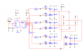
For now may proposition is to go with fullbridges as RB said. In order to save some transistors I used halfbridges and the starpoint
between the coils is being switched between GND and 12V.
As you can see the current passes directly from 12V to GND through 2 MOSFETs, i.e. the coils are not in series.
There is no need to have two coils on one bolt. You could use the coils the way you made them.
I still wonder why 13.8V and 0.7Ohm result in 1A. What am I missing? This is DC right?
I made a short description of how the circuit works. It should rotate the poles as described by RB. It uses P-channel MOSFETs and n-channel MOSFETs and two CMOS ICs in addition to the 555/4017.

For the random feature I don't know yet how to simulate this.. Unless someone else has an idea I will surely continue to think about it. The best option to get some pseudo-random behaviour would be a small uC...

Step 1 to 3: Q3 to Q5 are LOW, Q7 connects 12V to the star point of the coils
Step 4 to 6: Q3, Q4 or Q5 are HIGH, Q8 connects GND to the star point of the coils

Only one output of the 4017 is HIGH at a time.
output Q0 HIGH: T2 conducts, L1 and L4 are energized.
output Q1 HIGH: T4 conducts, L2 and L5 are energized.
output Q2 HIGH: T6 conducts, L3 and L6 are energized.

output Q3 HIGH: T1 conducts, L1 and L4 are energized, current flow is in the opposite direction now
because T8 conducts and the star point is connected to GND.
output Q4 and Q5 are similar. At the next step you are back at the initial position.
You could also add some LEDs to indicate what coil is energized and in what direction.


Attachments

Thread Starter

JCOX

Joined Nov 29, 2011
136
Praondevou,


Thank You so much, you have gone far beyond what I expected, I will consolidate the parts list tomorrow and get everything on order so I can get started on building this project.


I plan to go through mouser, I have ordered from there before.


If I may ask one other favor, after I make the list and before I put in the order can you verify it for me? Last time I ordered from them I accidentally ordered an extremely small hex inverter that I couldn't use, I don't want to do that again...


Thanks again everyone!!!
JCOX
 

praondevou

Joined Jul 9, 2011
2,942
Order the DIP package.

For the power part don't start right away with 12V. I recommend using a adjustable power supply for it, one with a current limiter function.

Do you have an oscilloscope?

I don't have the time to check this now. If you can wait a few hours I can check if there are cheaper options for the FETs.
Also recently I found that Futureelectronics was cheaper for every item I needed - compared to digikey. Never bought anything from Mouser.
You can have a look at www.findchips.com.
 
Last edited:

Thread Starter

JCOX

Joined Nov 29, 2011
136
I have time, no rush, I'm just excited to get started. no on the oscilloscope, there may be one I can borrow. I'll have to ask around.

I'll take a look at that website. I had np idea that you can buy packaged deals.
 
Last edited:

praondevou

Joined Jul 9, 2011
2,942
The Mosfet isn't as expensive as I thought. Between distributors there are however huge differences.
I didn't find a 4075 OR gate in a DIP package at Future. A NOR does it too. (4025)

Look at the attached comparison: Mouser vs. Futureelectronics

And Mouser wants $20 shipping cost. Are they out of their mind? The most expensive I saw till now was Newark with $15. Last time I paid $11 at Future.

You decide.
 

Attachments

THE_RB

Joined Feb 11, 2008
5,438
As a suggestion to simplify the hbridges, you could just buy three L298 ICs, each of those is a h-bridge and should run one coil pair. I think that would still demonstrate to the students what is happening.

Someone suggested the L298 IC earlier. :)
 

praondevou

Joined Jul 9, 2011
2,942
As a suggestion to simplify the hbridges, you could just buy three L298 ICs, each of those is a h-bridge and should run one coil pair. I think that would still demonstrate to the students what is happening.

Someone suggested the L298 IC earlier. :)
Yep that's another possibility. Makes the circuit physically smaller. They are available at Futurelectronics for $2.75 each. You need two of them.

If you use them you would not need the NOR gate but still the inverters (4049).

Have a look at the datasheet. In1 would be connected to one output of the 4017, In2 to the same output, but inverted. Two coils need then to be connected in series between Out1 and Out2 (as discussed earlier). I personnally never used the L298 before, many people here did though, so I don't think there would be a problem using them.

Btw, that's still only 6 coils in total.
 

praondevou

Joined Jul 9, 2011
2,942
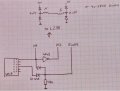
If using the L298 the easiest is to change the supply voltage for the LMC555 and
the 4017 to 5V. You can use a LM7805 voltage regulator for that. Refer to figure 7.

The VSS pin of the L298 will also be connected to 5V. The L298s' VS pin will be connected to 12V.

I drew the power part manually and only for one coil pair. The other 4 outputs of the 4017 need to be connected in a similar manner to the other two H-bridges. The logic inputs of the unused L298 H-bridge (in the second chip) will be tied to GND. There are 2 H-bridges inside a L298, so you need 2 ICs.

I don't have this component in my library and it's quite some work to make a custom one.

The circuit gets slightly cheaper and physically smaller. You only need to add the LM7805.

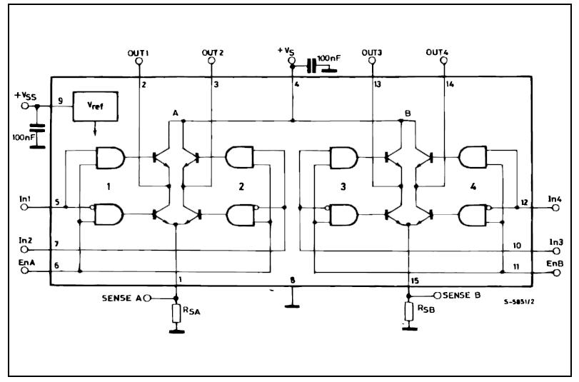
Refer also to the datasheet of the L298, figure 6.


That's the internal diagram of the L298.


Any questions just ask.;)
 

Attachments

Thread Starter

JCOX

Joined Nov 29, 2011
136
I was overly swamped at work for it being only a Monday. I didn't have time to putz around on the net. As for the L298 I was stoked to know that I could do this project with one 12 volt source, I think that I will stick with the 12v and leave it alone.

I have a "maybe" on borrowing a oscilloscope, I need to make a phone call tomorrow and see if they will allow me to borrow it, however once I have it I may need some guidance on how to use it...

I'm pretty sure that by now you've come to the realization that I'm barely keeping my head above water with all this. I can read your schematics, follow the current, understand what's being done (to an extent) But without your help this would have been a pipe dream, and I can't thank you enough, I definitely have a hunger to learn a lot more.

I've told the other instructors about your help and they can't wait to see a working component.

Anyhow, looks like Futureelectronics is much cheaper, will I be able to get everything from them? Your parts list was missing some things, I assumed that they were pretty common.

I was going to attempt this on a "bread board" (not the student one where you can use it for many projects), I was going to solder everything in. Would that be a good idea or is there another way? I don't know if I want to go all out and make a circuit with acid etching and everything... right?

What is the purpose of the hex inverter buffer (4049)? I know I have a few other questions but I can't think of them right now.

JCOX
 

praondevou

Joined Jul 9, 2011
2,942
Anyhow, looks like Futureelectronics is much cheaper, will I be able to get everything from them? Your parts list was missing some things, I assumed that they were pretty common.

I was going to attempt this on a "bread board" (not the student one where you can use it for many projects), I was going to solder everything in. Would that be a good idea or is there another way? I don't know if I want to go all out and make a circuit with acid etching and everything... right?

What is the purpose of the hex inverter buffer (4049)? I know I have a few other questions but I can't think of them right now.

JCOX
I only looked up the chips and transistors.
I hope you have a store nearby in case the gate resistors need to be adapted.
No acid etching. Just a stripboard/veroboard.

The 4049 is there to turn the p-channel FETs off when the corresponding output of the 4017 is LOW. The p-channel FET gate has to be HIGH (at source voltage which is the pin tied to 12V) to be OFF.

I have maybe an idea for a (pseudo) random feature, but I need to check it first... It would add 3 ICs probably.
 
Last edited:

Thread Starter

JCOX

Joined Nov 29, 2011
136
I only looked up the chips and transistors.
I hope you have a store nearby in case the gate resistors need to be adapted.
No acid etching. Just a stripboard/veroboard.

The 4049 is there to turn the p-channel FETs off when the corresponding output of the 4017 is LOW. The p-channel FET gate has to be HIGH (at source voltage which is the pin tied to 12V) to be OFF.

I have maybe an idea for a (pseudo) random feature, but I need to check it first... It would add 3 ICs probably.
really? That's awesome! should I wait to order everything then?
 

praondevou

Joined Jul 9, 2011
2,942
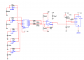
Ok here comes the random part. Of course it's not true random, but a random sequence of 16 voltages that are
used to modulate the 555.

There are 4 CMOS oscillators on the left. They are not synchronized, component tolerances will therefore
lead to constantly changing phase shifts between them. Then there is a 2 seconds oscillator at the top left side.
This will provide a clock signal to the D-flipflop.

--> In other words, every two seconds the outputs of the D-flipflop will change according to the current
state of the CMOS oscillators. This will be quite random since they run at a few hundred kHz.

The 4 flipflop outputs go then to a binary weighted summing amplifier. It's output voltage changes between
about 8V and 2V. This signal is used to change the 555s frequency (that's the same 555 from the other circuit.)

I suggest using a 20k trimpot for the 15k resistor and a 100k trimpot for the 100k resistor. Also the 220k
oscillator resistor could be 500k trimpot (or 200k + 100k in series), that gives you room for adjustments.

I added a 100 Ohm resistor at the discharge pin of the 555 because the simulation gave me too short
pulses which didn't get down to zero. I don't know if it is really necessary but it won't hurt if you put it in there.

I'm quite sure that the component tolerances are enough to get the random effect but you could buy
some 100 Ohm resistors too, they will allow you to change the oscillators frequency in case you need to.
(they cost almost nothing)


Attachments

praondevou

Joined Jul 9, 2011
2,942
As for the L298 I was stoked to know that I could do this project with one 12 volt source, I think that I will stick with the 12v and leave it alone.
JCOX
In case you misunderstood that part, the 5V regulator is not an additional external power supply. It's a 3-terminal IC in a TO220 package.
12V in , 5V out.
 

shortbus

Joined Sep 30, 2009
10,049
@JCOX - While waiting on your parts and final circuit, here is something else to consider/work on. You will need a way to hold your magnet and allow it to spin. I'm pretty sure that just laying a magnet on the top plate of the 'project' is going to make it spin when power is applied.

A rotating motor of any type needs a central shaft, to keep the rotor(magnet in this case) from being thrown out of the stators/fields rotating magnetic force. With out a pivot point it is going to attract the magnet to the most powerful coil and stop rotating. And with hand wound coils one of them is bound to be stronger than others. Just something to think about.
 

shortbus

Joined Sep 30, 2009
10,049
@Prandevou, I must of missed something in this thread, or maybe it was in a PM with you and JCOX.- Why a random voltage generation for the 555? I thought this was to simulate what is happening in a electric motor? Sorry for asking such a dumb question, but I'm lost now. :)
 

praondevou

Joined Jul 9, 2011
2,942
@Prandevou, I must of missed something in this thread, or maybe it was in a PM with you and JCOX.- Why a random voltage generation for the 555? I thought this was to simulate what is happening in a electric motor? Sorry for asking such a dumb question, but I'm lost now. :)
No problem at all. I'm glad someone else is looking at this.

Have a look at post 20. The OP wants an option to have the "motor" automatically changing speeds, in a random looking fashion.

JCOX, you will need of course something to disable the random thing, but that can easily be done with a switch. Buy a DIP switch too. Or maybe 2, you never know. Something similar to this: http://search.digikey.com/us/en/products/210-2MS/CT2102MS-ND/2503779
 

Thread Starter

JCOX

Joined Nov 29, 2011
136
oops, didn't mean to post yet. I'm in the process of compiling the order and have a few questions.. I will post in a few minutes...
 
Last edited:
Top