Electrical transformer model

Thread Starter

leo0001

Joined Sep 30, 2018
79
Hi,

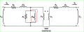
Here is an electrical model of a transformer :
upload_2019-5-6_16-50-41.png


A ferrite datasheet provides a coefficient to compute the primary inductance and the secondary inductance in function of the number of turns.

I would like to know what is the link between the magnetizing inductance, and the primary inductance ?

Actually I do not understand what is physically the magnetizing inductance...

Thank you and have a nice day


Léo
 

Attachments

Last edited:

Thread Starter

leo0001

Joined Sep 30, 2018
79
According to my research, the magnetizing inductance is a parasitic element which is due to the fact that the permeability of the core is not equal to infinity. So in order to estimate the magnetizing inductance, one way is to know what is the permeability of your core under the operating conditions of your transformer and you can compute it by knowing also the cross section area of your core and the magnetic path length.

Here is a link to help you.
https://www.ieee.li/pdf/introduction_to_power_electronics/chapter_12.pdf

I really don't know what is the precision of this calcul. In any case it will be really hard to know what would be the permeability of your core because it depends on temperature and on flux density applied on it and it may be dependant on other parameters...

The best thing to do is probably to measure it... :(

Good luck.
 

BR-549

Joined Sep 22, 2013
4,931
It depends on what you are doing.

Is this for a component model for a sim?

Is this homework?

Or are you trying to physically understand a transformer?

Or are you trying to mathematically understand a transformer?

Or are you trying to physically build a transformer?

All of these have different answers.
 

Thread Starter

leo0001

Joined Sep 30, 2018
79
I will tell you what I think but i'm not really sure of this...

I would say : "No". According to a better electrical model of the transformer the magnetizing inductance is located here (yellow)
upload_2019-5-7_21-6-34.png
Actually, the best thing to do is to forget inductance for a moment and think the transformer as a magnetic circuit. The flux is the current, the resistance is the reluctance which is inversely proportionnal to the permeabilty and the magnetomotive force is the voltage (magnetomotive force is proportionnal to the current into the windings). The goal of a transformer is to transfer all the created flux from the primary to the secondary.
For this you need a magnetomotive force, which is created by the primary windings. This will induce a flux (actually there is something a bit weird here because in a SMPS we applied a voltage during a certain time into the primary winding and then a current is passing through the primary winding, and according to Faraday's law, voltage induced flux, so i would say flux implies magnetomotive force... I don't know...). However the flux see a reluctance into the transformer. And if the permeability is not infinite the reluctance is not equal to 0. So a magnetomotive force would appears accross this reluctance. (like a voltage appears accros a resistance when a current flows through it).Here is the answer, it is possible to define the inductance by the following definition L = winding_number/reluctance. (You can find this relation thank to Ampere's Law and Faraday Law's). So Lmag is an image of this magnetomotive force that you can't recover from the secondary and which is lost "into the primary winding" due to the fact that the core has not an infinite permeability.

Magnetizing inductance produce a flux into the transformer, this "magnetizing flux" is always present into the transformer if a current pass through the primary windings but it is impossible to recover the flux produced by this magnetizing inductance. So you have to produce a higher flux than this minimum flux thanks to the primary windings in order to see a voltage on the secondary...

Thank you,
 

Attachments

Thread Starter

leo0001

Joined Sep 30, 2018
79
I'm actually trying to build physically a transformer and i would like also to simulate it. But i'm actually trying to understand everything about it :D

Thank you for your answer ! :D
 

BR-549

Joined Sep 22, 2013
4,931
To build one, two lengths of wire is all that is necessary.

To simulate one, all you need is specs.

To understand how one works, you need a generator, an amplifier, a variable load and a scope set up to image the B-H saturation curve.
 

Thread Starter

leo0001

Joined Sep 30, 2018
79
The flux is constant if the product Vin time duty cycle is constant and it is independant of the load like you write. What do you want to mean about the previous assertion ? I saw you say the flux on the core is constant so the flux generated by Lmag is the flux into the core. That's not true. The flux into the core is contant but it is equal to the sum of the flux generated by Lmag phi1 and to the flux generated by the primary inductance Phi2. Phicore = phi1 + phi2. Actually when you design a transformer, you know what voltage you want to have on the secondary so you compute what you will be the necessary flux in order to have the voltage required on the secondary. Nevertheless if you unload the transformer, the flux would be equal to the flux generated by Lmag. It is often say that Lmag "set up" the flux into the core.

BR-549,

Can you be more precise ? I have specs : voltage from the primary and voltage on the secondary, temperature rise, power loss, ambiant temperature... But i do no not know how this can give me the magnetizing inductance. The magnetizing inductance is dependant on the core that I select for having a certain power loss, rise temperature, EMI, secondary voltage ...

Thank you,
 
Last edited:

BR-549

Joined Sep 22, 2013
4,931
I have never used a sim, wouldn't know what specs or model information is needed.

Tell us about your function.

What is primary voltage and frequency?

What is secondary voltage and current?

Data sheet on core?
 

Thread Starter

leo0001

Joined Sep 30, 2018
79
I can give all you want ... But It would be better to give me directly the method to find the magnetizing inductance ?

My primary voltage is V1
My secondary voltage is V2
My frequency is Fsw

My core is a planar transformer with a cross section area Ae, a permaebility µ, a magnetic length le... The permeability is dependant on the temperature T and flux density B

Thanks,
 

BR-549

Joined Sep 22, 2013
4,931
All righty then.


1. Use DC power to measure resistance R of primary.

2. Measure current by applying known Ac in primary coil while secondary coil is open-circuit.

3. Find total impedance Z from step 2 using V rms and I rms.

4. Find inductive reactance Xl by subtracting R from Z.

Z^2=R^2+Xl^2

5. By finding Xl use below formula to find inductance L.

Xl=2πfL
 

Thread Starter

leo0001

Joined Sep 30, 2018
79
Hi,

Thank you for your answer, but I try to build one and i can't measure it as you can read from the previous message. I would like to estimate it.

Have a nice day !

Léo
 

Thread Starter

leo0001

Joined Sep 30, 2018
79
Hi,

Thank you for your link :D

How can you say that my transformer is linear ? The BH curve of my core is actually non linear and there is an hysteresis loop. Actually i'm confused... I never see a core with a linear permeability.

I took a look of your web site. I didn't see how do you compute the magnetizing inductance ?

Thank you very much,

Léo
 

Bordodynov

Joined May 20, 2015
3,431
First of all. Why do you need this inductance? Everything can be calculated without it.Secondly. You operated on relative magnetic permeability. From this I concluded that the core is linear. For a non-linear core, permeability varies greatly.Thirdly, a model with a nonlinear core with hysteresis is simply constructed. You just need to take another core from my library.I use the core, which is used in my example, as a first approximation. Then I replace it with a non-linear one. And this allows you to build magnetization reversal curves and power to the cores (due to hysteresis).
tra2.png
 

Thread Starter

leo0001

Joined Sep 30, 2018
79
Thank you very much for your help !

I need to estimate it in order to size a component on my electronic board. Actually i'm using an High side active clamp for reseting the core in order to prevent it to saturate in a Forward topology. It allows to reduce stress on VDS by applying a voltage thanks to a capacitor and an IC on the primary when the main mosfet is switch off. However the capacitor is charged by the magnetizing inductance. If the capacitor is too low I will have a lot of ripple and so unecessary high voltage on VDS, however if the capacitor is too high the transformer will be badly reset during transient load...

upload_2019-5-10_20-47-39.png
Normally, In a good world the magnetizing inducance should be very high and the magnetizing current should be low... Actually I'm not able to find this kind of result. My magnetizing inductance is lower than my primary inductance :(

Thanks you,
 
Top