Electric fencer output transformer

Thread Starter

cpgos

Joined Nov 26, 2018
21
Ciao,
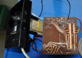
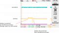
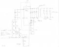
I would appreciate some help with an electric fencer that I am attempting to repair, see attached file for the circuit diagram that I have put together.

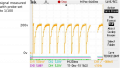
The fencer does not output a high voltage pulse even though the charging and discharging of capacitor C1 seems to work. Also, both primary and secondary coils of the output transformer seem to be intact; the secondary gives a output when energised with a sinewave.

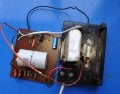
Is the output transformer in a device such as this any different from a standard power supply transformer? Any comments or suggestions appreciated.

Best regards.
 

Attachments

Hymie

Joined Mar 30, 2018
1,277
Rather than looking at the voltage across capacitor C1, you need to look at the voltage across the input to the transformer (black and brown).
 

Thread Starter

cpgos

Joined Nov 26, 2018
21
Rather than looking at the voltage across capacitor C1, you need to look at the voltage across the input to the transformer (black and brown).
Thank you for your response.
I will do as you suggest and be in contact again on Monday with the result.

Best regards
 

ebp

Joined Feb 8, 2018
2,332
Assuming the test with AC was done with the transformer out of circuit, my first suspicion would be the diodes across the primary. If any one has failed short-circuit or somehow degraded to lower than normal reverse breakdown voltage (which would be very unusual), then the energy from the cap will not make it into the transformer. The other possibility is that the capacitor itself has failed in some fashion greatly reducing its capacitance. This is also unlikely but there are mechanisms by which it can occur. I'm assuming it is a film type capacitor. If it is an electrolytic type, reduction in value over time is fully expected - they do "wear out."

Depending on the power level, the transformer is likely to either use a gapped core. Their design is usually closer to that of an automotive ignition coil than to a conventional transformer used for low frequency AC.
 

Dodgydave

Joined Jun 22, 2012
11,285
Looking at your circuit, the Thyristor Cathode has no path to Neutral , so it won't fire.

I think your drawing is wrong.

Better to post pictures of the circuit board.
 

Thread Starter

cpgos

Joined Nov 26, 2018
21
Assuming the test with AC was done with the transformer out of circuit, my first suspicion would be the diodes across the primary. If any one has failed short-circuit or somehow degraded to lower than normal reverse breakdown voltage (which would be very unusual), then the energy from the cap will not make it into the transformer. The other possibility is that the capacitor itself has failed in some fashion greatly reducing its capacitance. This is also unlikely but there are mechanisms by which it can occur. I'm assuming it is a film type capacitor. If it is an electrolytic type, reduction in value over time is fully expected - they do "wear out."

Depending on the power level, the transformer is likely to either use a gapped core. Their design is usually closer to that of an automotive ignition coil than to a conventional transformer used for low frequency AC.
Thank you for your response.

I will check the diodes across the primary on Monday next and also post some photos of the transformer.

During my initial investigation I replaced capacitor C1 with a new unit, though I did have to guess the specs; as this did not make any difference to the final transformer output the capacitor does not appear to be the problem.
 

Thread Starter

cpgos

Joined Nov 26, 2018
21
Looking at your circuit, the Thyristor Cathode has no path to Neutral , so it won't fire.

I think your drawing is wrong.

Better to post pictures of the circuit board.
Thank you for your response.

The drawing could easily be wrong, I will post some photos of the circuit board on Monday next.
 

Thread Starter

cpgos

Joined Nov 26, 2018
21
Thank you for your response.

The drawing could easily be wrong, I will post some photos of the circuit board on Monday next.
Ciao,
Please note the attached screenshot of the capacitor voltage and photos of the circuit board.

There is no voltage signal across the primary of the transformer, ie the brown and black wires.

Also, the thyristor is a C122D which I temporarily replaced with an MCR72-8, see Farnell 774-3559; as this did not result in any improvement in the final output of the transformer the C122D was put back into the circuit.

Any further suggestions appreciated.

Best regards
 

Attachments

Thread Starter

cpgos

Joined Nov 26, 2018
21
Ciao,
Please note the attached screenshot of the capacitor voltage and photos of the circuit board.

There is no voltage signal across the primary of the transformer, ie the brown and black wires.

Also, the thyristor is a C122D which I temporarily replaced with an MCR72-8, see Farnell 774-3559; as this did not result in any improvement in the final output of the transformer the C122D was put back into the circuit.

Any further suggestions appreciated.
PS : I forgot to mention in my previous post that all of diodes D1 to D5 seem to be ok, the gave ~0.5V forward bias on a digital multimeter when checked.

Best regards
 

LesJones

Joined Jan 8, 2017
4,174
From the capacitor waveform I think the SCR is triggering but discharginginto a short circuit. I suspect that one (Or more.) of the diodes in parallel with the transformer primary are short circuit. Remove the mains power. Discharge the capacitor C1. Disconnect one of the wires to the transformer primary. (Black or brown.) Measure the resistance across the diodes that were connected in parallel with the transformer primary.

Les.
 

Thread Starter

cpgos

Joined Nov 26, 2018
21
From the capacitor waveform I think the SCR is triggering but discharginginto a short circuit. I suspect that one (Or more.) of the diodes in parallel with the transformer primary are short circuit. Remove the mains power. Discharge the capacitor C1. Disconnect one of the wires to the transformer primary. (Black or brown.) Measure the resistance across the diodes that were connected in parallel with the transformer primary.

Les.
Thank you for your response.

I checked the diodes in parallel with the transformer primary and found them all to be ok. They all seem to have a forward voltage of ~0.5V.

Best regards
 

LesJones

Joined Jan 8, 2017
4,174
After reading all the other posts again I think there oare only three possible explanations.
1 One of the diodes is breaking down far below it's reverse voltage rating. Test the diodes at close to their reverse votage rating by connecteng them to a power supply about this value via a current limiting resistor, (Chose a value that would limit the current to about 5mA into a short circuit.
2 Shorted turns on the primary or secondary of the transformer. It would be very difficult to do this without a known good transformer from another one of these units to compare it to.
3 One of the 33K resistors across the secondary has gone low value.

Les.
 

ebp

Joined Feb 8, 2018
2,332
Are the diodes marked with a type number?
There is some chance they are zeners. If they are, there might be a chance that one of them is conducting far below its nominal voltage, though I think this is extremely unlikely without it having failed short circuit.

Les's comment just popped up. I also think a shorted turn might be the problem. This is something that can sometimes be tested by taking the transformer out of circuit, applying a DC voltage to the winding and seeing if the transformer "rings" when the voltage is removed. A pulse or square wave generator can be used through a resistor (to reduce loading when ringing would likely occur) or you can do something as simple as using a 1.5 V dry cell and just manually connecting then disconnecting it. Your digital scope will be a great help in allowing you to see if there is ringing, A shorted turn will prevent more than very brief, low amplitude ringing. Normally you will get a fairly long ring-down as the transformer inductance resonates with the capacitance of its windings. If you can, deliberately adding a shorted turn (any fine wire that you can get around the centre leg or even one of the outside legs of the transformer core in any way will do) can help to distinguish the effect. If it makes very little difference, there probably is a shorted turn, If it makes significant difference, there probably isn't a shorted turn. This is a quite subjective without a known-good transformer for comparison.
 

Thread Starter

cpgos

Joined Nov 26, 2018
21
Hi ebp,
I have never thought of testing for shorted turns that way. I like it.

Les.
Thank you for your further responses.

The 33k resistors are ok giving a combined resistance of 13.78k.

The attached file shows the result from a check on the output transformer with a 1.5v battery, a 0.5R resistor and a switch. Channel_1 was connected across the primary and channel_2 on the secondary. Is the wiring as you intended and can anything be concluded from the results?

As yet I have not checked the diodes with a high voltage, they have only been checked with a multimeter.

Best regards.
 

Attachments

LesJones

Joined Jan 8, 2017
4,174
My feeling is that the transformer has shorted turns as I can see no sign of pulses when the battery is connected and disconnected on the secondary.The ringing would be on the edje when the battery is disconnected but as the scan speed is so low you will probably not see it. I don't have digital scope and have never used one so I dont know it is possible to capture a single event. If you can do that then you could trigger on the negative going edge and use a faster scan rate. If I was doing the test with my analogue scope I would pulse the drive to the primary with a high voltage rating transistor driven by a pulse generator so the transition would be visible. The pulse width and repetition frequency could be adjusted to match a scan speed that showed the ringing. If you can get a display to show the ringing then adding a shorted turn as ebp suggests should give you a better idea of if the transformer does have shorted turns. Adding a shorted turn was the trick that I never thought of, I was thinking of comparing the ringing on a known good transformer with the suspect one.

Les.
 

Thread Starter

cpgos

Joined Nov 26, 2018
21
My feeling is that the transformer has shorted turns as I can see no sign of pulses when the battery is connected and disconnected on the secondary.The ringing would be on the edje when the battery is disconnected but as the scan speed is so low you will probably not see it. I don't have digital scope and have never used one so I dont know it is possible to capture a single event. If you can do that then you could trigger on the negative going edge and use a faster scan rate. If I was doing the test with my analogue scope I would pulse the drive to the primary with a high voltage rating transistor driven by a pulse generator so the transition would be visible. The pulse width and repetition frequency could be adjusted to match a scan speed that showed the ringing. If you can get a display to show the ringing then adding a shorted turn as ebp suggests should give you a better idea of if the transformer does have shorted turns. Adding a shorted turn was the trick that I never thought of, I was thinking of comparing the ringing on a known good transformer with the suspect one.

Les.
Thank you for your response.

The attached file shows a screenshot using the same setup as previously but with 250ms/cm rather than 1s/cm. Could the small spikes on the secondary be an indication of the ringing that you are looking for?

I will repeat the test tomorrow with a transformer that I know is working.

Best regards
 

Attachments

LesJones

Joined Jan 8, 2017
4,174
I would expect the spikes to be higher on the secondary as it is a step up transformer. (I would expect a ratio of at least 1:10) The ringing (If it is present.) would be hundreds or thousands of hz so need a sweep speed of about 1 ms per cm.

Les.
 

Thread Starter

cpgos

Joined Nov 26, 2018
21
I would expect the spikes to be higher on the secondary as it is a step up transformer. (I would expect a ratio of at least 1:10) The ringing (If it is present.) would be hundreds or thousands of hz so need a sweep speed of about 1 ms per cm.

Les.
The digital scope that I am using also has the ability to save the waveform that the screenshots are based on, see attached files. The sample rate is 1kHz with the primary on ch_1 and the secondary on ch_2 as previously.

Also, I used a variac to check the operation of the transformer and found that with ~60Vp-p applied to the primary ~120Vp-p appeared on the secondary.

Does any of the above confirm that the problem is with the transformer as both are a long way from the expected ratio of 1:10?

Best regards
 

Attachments

LesJones

Joined Jan 8, 2017
4,174
I think that it only seems to behave like a transformer with a 1:2 ratio and the fact that there is no ringing shows that the transformer is faulty.

Les.
 
Top