EEG signal generator

Thread Starter

Eta

Joined Jun 8, 2024
2
Hello everyone!!! First of all I will tell you right away that I don't speak English so if I write something unclearly, I will be happy to explain myself better.
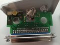
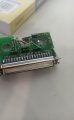
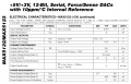
I have been asked to make a power supply for a calibration device for an EEG recording device. I made a power supply that feeds 3V into VDD and 1.5 into the reference. I went by trial and error but now I have to write a thesis and I should try to figure out what is in the device I fed. The device is out of production so I cannot access the technical manual. I only know that it emits 50 uV, 210 uV and 2mV sinusoidal signals. I attach below the pictures. Please help me out if you can. I am not an engineer, I am a technician new to the field and I only recognize the resistors...I need to figure out what components are showing and speculate how it works. Thank you!
 

Attachments

MisterBill2

Joined Jan 23, 2018
27,186
OK, what is missing is the frequency of the sine wave. And the output impedance. And the input impedance of the EEG machine. And the required accuracy.
a simple resistance capacitance oscillator powered by a regulated voltage , followed by a resistance voltage divider string.If the voltage at the top of the string will be 1.000 volts, then the divide ratio to provide the lower voltages will just be tedious arithmetic.
 

sparky 1

Joined Nov 3, 2018
1,218
A typical EEG (Electroencephalogram) signal, measured from the scalp, will have an amplitude of about 10 µV to 100 µV and a frequency in the range of 1 Hz to about 100 Hz12. some EEG use INA118 followed more op amps multiplying 10,000 times.
Since you need a calibration signal there is a division.

The oscillator is very low frequency between 1 Hertz up to 100Hz the average brain activity 8Hz.
An amplitude of 10 micro volts to 100 micro volts very small, very sensitive.

The divider can be enclosed and immersed for constant temperature bath.
I like a source using the LM334 and LM336 2,5V at 3mA. This can be reliable however circuit may use far less current.
The metrology is that when the thermal drift over time is minimal the measurement of the output is compared to a standard.
If you have access to a precision voltmeter that might be adequate. The op amp mentioned could be set to multiply 100 times.
That is, the INA118 could be used to multiply 10mV to 1V measured with a precision meter but later used to multiply 10uV
This recorded multiplying factor can be used together with a precision voltmeter as an extended range to get more accuracy.
This same instrumentation op amp that amplifies an EEG signal is used to amplify the calibration signal and when they are equal
then your close and close can be improved upon.

If the calibrator is slightly more or less than 10 uV but it is stable you can record that value.
Finally you adjust the temperature very slightly and patiently to get a closer calibration.
The confidence of error is when a known source is compared to the source you are making.

There is terminology that relates the older analog and newer digital types.
The role of the differential amp[ifier, the repeatability by using same placement handling procedures of the electrodes.
EEG Montages: Part 1 - Differential Amplifiers (biosourcesoftware.com)
 
Last edited:

MisterBill2

Joined Jan 23, 2018
27,186
OK, and many thanks to Sparky1 for more explanations.
So it looks like a simple system would be able to verify that the EEG system is functional but not able to show it is accurate. So now again the question of "How close to exactly right" is "Close Enough" is adequate.
 

Thread Starter

Eta

Joined Jun 8, 2024
2
Thank you both for your answers, you were super quick! I am studying everything you have written. The informations I wrote are the only informations I have. Fortunately, I don't need to do the exact mathematical calculations of the circuit but only to identify the components and hypothesize the operation of the circuit. Now I am trying to study how the Wien's bridge works.
You have been a great help!
 

Irving

Joined Jan 30, 2016
4,996
Welcome to AAC. What are the two integrated circuits on the board? Where are you plugging in the 3 and 1.5v, on the D-sub connector?
 

MisterBill2

Joined Jan 23, 2018
27,186
Unfortunately the photo of the circuit board assembly is out of focus and also too dark to be able to read the part numbers on the ICs. So the TS will need to use their magnifier and a good light to see all of the characters and provide that information.
MY guess is that the single "D"connector provides both the power connection and also the various signal level connections. The reason for selecting that connector is that there is none cheaper that is commonly available.
 

sparky 1

Joined Nov 3, 2018
1,218
In material possibly dated later.
A square wave oscillator used as reference, the probes initial amplitude and second output to the recorder,
The power supply should be checked for stability and noise tolerance.
The pen recorder specs and procedures manual would be helpful.
The circuit would produce evenly on all channels.
The EEG standards at the time that it was made.
Setting the correct scaling factor.
The first article describes a comparison of a pair of electrodes using a differential amplifier.

Technical aspects of EEG | MedLink Neurology
https://www.acns.org/pdf/guidelines/Guideline-1.pdf
 
Last edited:
Top