Eddy Current Retarder Help

Thread Starter

Rocketman12

Joined Apr 20, 2022
13
Hi Everyone,
Looking for some assistance driving an eddycurrent retarder.
My Skills - I have some basic soldering skills and some limited understanding of circuits and their components. Enough to build a timer circuit with Resistor/capacitor and understand basic logic chips jk flipflop ..etc Not enough to build a circuit that uses them. I can write software in many languages.

Essentially I have a very old Dyno for tuning race cars. It has a retarder in it.
This is connected to a slotted disc (12 slots read by optical circuit (Sensor).
This connects to a torsion spring.
This connects to another slotted disc and sensor.
This connects to the roller that the wheels go on.

The current circuit boards used a lot of old chips (1980's) that would measure the rotational speed of 1 disc. It would use the jk flipflop chips to determine the difference in position between the 2 discs. With that information is calculates speed and torque. It feeds a speed signal to a second board that drives the retarder to limit the speed in a desired range.

All the boards are fried so I have purchased an arduino and programmed it. I calculate speed and load based on the input sensors and send a PWM signal output with my desired load for the retarder. This is where I need help -

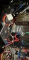
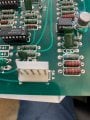
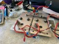
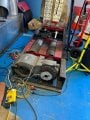
How do I drive the retarder with my PWM signal? I have approximately 40v coming from the existing transformer. As per the attached pic there is a small circuit board that sends 2 signals to 2 plates (On the left) each plate has
diode and a triac/SCR 2N3898. The SCR connector goes back to the main driver board on the SKA connector. The 2 signals are fed from the 2 resistors just to the right of that and the source of the resistors is the same rail.

So I hope that's enough for someone to understand what's going on. I have purchased one of these in the hopes that it might be what I need. I basically need to know how to take my PWM output from my arduino and drive the retarder through the small circuit board or directly to the plates. I can wire, I can solder. I just can't design the circuit.

Thankyou for any advice. An entire club of race car drivers would sincerely appreciate your help.
BTW we are only driving 1 coil on the retarder.
 

Attachments

MisterBill2

Joined Jan 23, 2018
18,462
First question is why you think that the older boards are "fried"? It may just be a case of not knowing how they work. The retarder varies the load by adjusting the magnetic field. So the PWM signal will need to vary the voltage to set the current. That can consist of a rectifier diode charging a capacitor that charges up and biases a transistor to drive the retarder coil.
If you can get hold of the manual and service for an older SUN ELECTRIC roller dyno you can simply copy that circuit. It will not be the most efficient but it will work. In fact, your old system might even BE an old Sun Dyno.
 

LowQCab

Joined Nov 6, 2012
4,063
Without a Schematic it's all a guessing-game.
It might even be worth it to design a whole new Control-System,
it would certainly be more efficient than what you've got.
.
.
.
 

MisterBill2

Joined Jan 23, 2018
18,462
Aside from a circuit, the eddy current brake does not use PWM to vary the power. It used a phase control circuit, it appears. Triacs and AC controls are phase angle, not PWM. So with a bit of experimenting you should find that the resistance torque is controlled by a DC voltage controlling the triac circuit. At that point you will need to go from the arduino PWM to an isolated DC voltage to control the triac firing angle. With any luck you will be able to use the same power control assemblies and have it working.
 

Thread Starter

Rocketman12

Joined Apr 20, 2022
13
Thank you both so much for your time.
MisterBill2 I believe what you are describing is the desired result. Due to lack of knowledge on my part, the things I don't understand are -
1 What voltage do I need to drive those triacs on the metal plates,
2 Do I have to bring them to ground between pulses.

I was toying with the idea of one of these
Arduino Compatible 24V 5A MOS Driver Module | Jaycar Electronics
But do I need to send 40/80 volts to the triacs as that's what is connected to those plates.

P.S. a lot of smoke escaped from several of the boards inside the dyno. Many cooked ICs and Caps. It's Australian (Vane VP930) and seems that no Schematics exist. I felt it best to come up with a replacement for the main parts.

Once again thank you.
 

MisterBill2

Joined Jan 23, 2018
18,462
At this point there is a problem because there are a few different schemes for controlling triacs. Those schemes require different sorts of input control inputs. To know what input is required to control a circuit requires understanding that circuit, at least partly.
So I am thinking that I need to see if I can find any information about the Sun Electric Dynomometer control. I think that the setup was similar to the one that you have.
One more thought: Would this dyno be used for acelleration evaluations. or for steady speed evaluations? That will affect how fast it needs to respond to changes.
Another concern is that the smoke from several boards does not appear to have been from the boards in the pictures. And none of the pictures appear to include the power source for operating the eddy current braking coil. So there is some information missing .
 

Sensacell

Joined Jun 19, 2012
3,442
If you can determine the characteristics of the magnetic coil, you should be able to drive it with a MOSFET and a fast power diode in direct PWM mode.
This might be more straightforward than diving into the complexities of the existing TRIAC circuit, which may be dead as well.
 

Thread Starter

Rocketman12

Joined Apr 20, 2022
13
I was trying to keep it a simple as I could.
Attached are 2 pics. No1 is the board that reads signals from the 2 light pulse discs on either side of the torsion spring. The top part of the board seems to be for calculating speed and sending it as a measured voltage to the outputs on the right.
Just below that are some other calculations to check the time difference between the discs and output a torque value. (I was measuring voltage from TP7 to go into our dyno computer system.
The lower half of that board applies a bunch of calculations and amplifications to send to a lcd display on a hand controller.

No2 is the power supply and driver board for the retarder. This receives info from the No1 board regarding speed and measures it against a set speed (Variable voltage from hand controller). It then works out how much to npower the retarder. It does a bunch of other things like operating air brakes ..etc that I don't need. Down at the very bottom right of this board is the other pic I sent originally with the 2 resistors and the connector for the small skr module.

We fixed and tested the power supply. Also temporarily replaced it with 3 workbench power supplies set to appropriate voltages. and could not get the No1 board to stop blowing chips. Replaced all caps. Replaced all electrolytics. Replaced all ICs. and a couple of burnt out resistors. I had help at that point. But got to the point where they needed a schematic to source the problem. The lower board may work after our repairs but as there is no speed signal coming down we can't test it.

Figured if I could bypass everything and use the arduino it would make it a bit future proof.

I don't really understand the 2 plates with triacs on them. They are coupled by a thermistor.

There is a large transformer in the original post which connects to 240v and the 2 outputs to the metal plates. The 2 wires to the retarder also come from the same picture. I will try to draw a diagram of that circuit when I get back to work on tuesday. Unless I find the right pictures on my phone in the morning.
 

shortbus

Joined Sep 30, 2009
10,045
First off is this really a dyno? I know some of the Telma's can be made to work as a dyno, their biggest use is big truck, semi truck brakes. I think most Telma controllers are still available as replacement parts. As a dyno they wouldn't be able to withstand very long pulls without cooling.

Here is a PDF of one of their real dyno controllers - https://www.telmausa.com/Downloads/TL133013.pdf
And just a quick read shows that the control is PWM to the brake.

Google gets many hits on Telma retarders for DIY dynos but not much about using the AE type.
 
Last edited:

LowQCab

Joined Nov 6, 2012
4,063
That's excellent that You found a Spec-Sheet,
but it doesn't show the Control-Schematic.
At least it makes it fairly clear just how easy a new MOSFET Controller could be built to replace the
noisy and crude SCRs.
Also, I would guess, based on the provided Graphs, that the original operating scheme
basically had just 3 different Torque curves that could be switched in or out.
With a new MOSFET Controller You would automatically have
seamless 0 to 100% Torque Control rather than 3 distinct fixed levels.

Next it would come down to getting some pictures of the various Sensors,
and with some luck, a Schematic for them too.

It's very likely that a new modern Strain-Gauge with known Specifications could be easily retrofitted,
and at the same time,
replace the Optical-Sensor on the Slotted-Wheel with a new one with known Specifications.
At that point you'd have a close to new Machine mechanically.

Then the next challenge would be to figure-out the most advantageous operating scheme,
and to design a Controller that will deliver the numbers You want, repeatably, and with reasonable accuracy.

Does this Retarder connect directly to an Engine that is out of the Car ?, ( it's rated to 5000-RPM ),
or is it designed to provide a variable amount drag, ( Torque ), to a weighted set of Rollers and
work as a combination Inertia + Torque Wheel Dyno ?
How many do You have ?, one or two of them ?

If it's a Roller setup, it would be advantageous to use a large Chain-Drive to
double or even triple the speed of the Retarder vs the Rollers.
.
.
.
 

MisterBill2

Joined Jan 23, 2018
18,462
What we can see from the two PDFs is that this is a system that can require a lot of current, and much power. 43 amps at 24 volts is a big deal. That also means that the system is a very big inductor and that will require a bit of caution.
My suggestion is re-arranging the coils so that all of them are in series. That will reduce the current draw at maximum load to one third of the 43.5 amps, and probably allow PWM operation directly off the rectified mains voltage. BUT the duty cycle will need to be kept below about 60%, which should be easy to do. Also, running it at a higher voltage and lower current will allow the use of less expensive mosfet transistors.
Now I am no longer suggesting trying to use the existing triac assembly. Possibly the transformer, but maybe not.
 

shortbus

Joined Sep 30, 2009
10,045
Now I am no longer suggesting trying to use the existing triac assembly.
That triac system is why I looked into this. The controller is probably a truck braking controller, not meant for a dyno. I use braking loosely they really aren't service brakes but instead like they are being called, a retarder, like when stopped at a traffic light.
 

MisterBill2

Joined Jan 23, 2018
18,462
No,it is an actual eddy current dynomometer brake, that uses the losses in the cast iron rotor to create the torque load. A rolls variation of this was sold by Sun Electric to use for emission testing cars at repair shops and dealers before the tests became simplified. This brake can work but they will need some serious cooling fans on it. By putting all of the coils in series the operating voltage can be tripled, presuming all of the coils are similar. This change will reduce the maximum required current to one third of the 43.5 amps stated in the specifications, while allowing the same power. The benefit will be a much simpler control scheme and power supply. This system should be able to function satisfactorily on unfiltered rectified mains power, with the free-wheeling protection diode serving as a filter to keep current flowing during the off portion of PWM control. So it does not seem that the filter capacitors in post#14 are really required, if the PWM frequency is selected correctly.
 

Thread Starter

Rocketman12

Joined Apr 20, 2022
13
Hi,
Stopped past work and snapped a pic today.
Yes it does have a serious fan and cooling.
It is a chassis dyno. Rolling road.
Has worked well for years until the computational boards let out their smoke.
The triacs and thermistor were also dead. Have replaced them with new ones.

The control box picture shows the transformer, plates and power input.
The other boards have been removed.
 

Attachments

LowQCab

Joined Nov 6, 2012
4,063
Interesting ..........
There are 2 Interrupter-Wheels, one on each side, do You have any idea why they need 2 ?

Also, 12-Holes amounts to fairly low resolution,
I think You ought to take the Wheels to a Machine-Shop and have them cut 36 rectangular "Slots" instead,
the Slots and the Teeth should be symmetrical so that "on-time" and "off-time" are equal,
that comes out to a 5-degree-Tooth, 5-degree-Slot, 5-degree-Tooth, 5-degree-Slot, ....... etc.

I'm thinking that getting any of this original stuff to work is a lost cause.

What type of device / mechanism is used to measure Torque on this Machine ?
It should be a Strain-Gauge mounted near the Retarder,
this must be replaced with a new one and calibrated perfectly, or nothing else matters.

If the mechanical stuff is in good operating condition,
the rest is up to the software-boys to figure out some Code.
It shouldn't be too difficult .........
1)
The Retarder-PWM-Circuitry needs a Feedback-Loop with PID-functions, and also
a Manual-Preset-Value function, and an automated Wheel-Acceleration-Ramp-Limiting-function which
applies enough Torque to the Wheels to create a "Pre-Set-Acceleration-Rate" of the Interrupter-Wheel
regardless of the amount of Torque being applied at any given moment.

High Acceleration-Rates will skew the numbers to a substantial degree because of the
added weight of the Rollers, which the Car must accelerate, unless performing a static-test-measurement.
This could be calculated, and factored in to the following math-calculations for producing absolute numbers,
or, just ignore this factor if the accuracy of the numbers is not all that important, but
repeatability, and the demonstration of a change between runs, is the only really important consideration.

2)
When the Acceleration-Ramp is started, then do this math-calculation .........
RPM X Torque, divided by 5250 = Horsepower, then display, and
create a Graph-Entry with current "Horsepower-Number @ RPM", and create Number on Computer-Display.
Do this calculation at least every XXXX number of Interrupter-Wheel-Pulses.

3)
When Acceleration-Ramp is started, then create Computer-Screen-Display of current Torque-value.
Create a Graph-Entry with current Torque-value,
refresh this number every XXXX number of Interrupter-Wheel-Pulses.

4)
RPM X Tire circumference in inches, ( Tire-Circumference must be manually entered ),
divided by inches per Mile, X 60 = MPH,
Create a Graph-Entry with current MPH-value,
then create Computer-Screen-Display of current MPH-value,
then refresh this number every XXXX number of Interrupter-Wheel-Pulses.

See super easy !!!!

The Software is the only real bugaboo here.

Software is available online for DIY Inertia-type Roller-Dynos, but I'm not aware of anything
being available for Constant-Load-type-Dynos, especially when it's incorporated into a Roller-setup.
.
.
.
 

MisterBill2

Joined Jan 23, 2018
18,462
The purpose of the two interrupter wheels is described in post #1. That is how the torque is measured. There is a spline-shaft between the disks that is twisted by the torque, altering the phase angle between the two sets of pulses. It is a reasonable and recognized scheme for measuring torque that avoids the expensive and delicate torque load cell and the associated instrument amp and strain-gage system, as well as the slip rings required with some torque measuring systems. So it is important to take care of that set of sensors, they measure a lot more than just speed.
 

Thread Starter

Rocketman12

Joined Apr 20, 2022
13
Thanks LowQCab appreciate the input and interest,
As mentioned in the original post I have built an arduino that accepts the inputs and outputs a PWM.
I have handled the inputs from both sensors on the 12 slot discs and can already calculate speed and torque. I have an algorithm used in Car cruise control to adjust the duty cycle of the PWM to achieve the required application or torque. I have already have a dyno software system that will produce runs and graphs based on the torque and speed output from my arduino. Essentially all the software is done, bar the real world testing. The dyno is built and and has previously worked (Now minus the bits that control the retarder) I have a good grasp on maths and software engineering.

What I don't know is how to take the PWM signal I have, use the transformer and triac plates(or not) and send some kind of power to the retarder to make it work. I come up short in knowledge in the electronics field. Could certainly solder the bits needed together and connect them, but don't understand how it works. Basically I have 2 rather thick gauge wires going from the plates shown earlier to the retarder at the other end of the dyno. If I have connect something to them that will engage the retarder and be controlled by PWM, I am home :)

For that matter if there is something better than PWM that I can output from arduino, I'm happy to code and connect that.
 

MisterBill2

Joined Jan 23, 2018
18,462
It will probably be the simplest to arrange all three sets of coils in series, first each pair in series as for the 24 volt arrangement, and then all three pairs in series, so that the full power will be at 72 volts and one third of the maximum current for the 24 volt connection. That will allow using a 400 volt 20 amp mosfet and a 400 volt 20 amp shunt diode for the coil so that the current does not stop when the magnetic field is collapsing because the diode is switched off. The power can come from the mains directly with only a rectifier, and not a lot of filtering. Probably a half wave rectifier will be all that is required, because the rated power will be at much less than 100% of the PWM duty cycle. You will need an isolated gate driver for the power mosfet, and probably a decent heat sink as well, but there is a lot of good application information available about that. Because the eddy current brake is a fairly large inductance it will probably need to have a lower PWM frequency so that the current can rise to the required level.
 
Top