Earth Fault Detection System

Thread Starter

Christopher Chan

Joined Jul 4, 2016
1
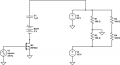
I have a 110V DC transmission line that's power a lot of monitoring equipment. I am trying to design a non-intrusive way of finding earth faults within the DC system. What I am trying to do is inject a 3V square wave into this transmission system. If there happens to be a fault in the system, then the square wave will lead me to the fault by forming a full circuit loop. I can then trace this loop using a Hall Effect sensor.

The image below is a rough sketch of what I am trying to do. Of course, there will be a lot of resistors, capacitors and inductors in parallel within the DC transmission system.

When I try to use an oscilloscope to find the square wave, I can only see intermitten vertical spikes. Also, does this design even work? Are there other designs out there that I should know of? Thanks.
 

Attachments

bug13

Joined Feb 13, 2012
2,002
I have looked at something similar before, here is the best I can find.

http://www.loopslooth.com/how to find ground loop.html

Here is what I understand it:
The basic idea is you couple a unique frequency into your power line through inductive coupling (like a transformer). If there is a ground loop, there will be current flow (with the same frequency of the signal you inject) through the loop. All you need to do is detect that current.

If you end up buying a meter form this website, I am interested to know how it works.
 

profbuxton

Joined Feb 21, 2014
421
A Company called "Bender" makes such systems. Used on rail signalling power supplies to detect earth faults since the supplies are "floating".
 

AnalogKid

Joined Aug 1, 2013
10,987
Based on your drawing I see a +/-55 Vdc power supply connected to both two independent single-ended loads (R1 and R2) and one differential load (R3+R4). Since there is only one ground symbol type, that means everything is common grounded. Finding "earth faults" means being able to measure a current to earth ground that is different from the currents to the power ground, so where does earth ground figure into your system?

Your image shows the test signal AC-coupled to only one side of the power system. If the goal is to see if it will appear on the other power rail, it will because of R3+R4. However, assuming the AC impedance of the power distribution is very low at only 25 Hz, the impressed signal probably will be way lower than 3 V.

Thinking about this a bit more... If the idea here is that there is some kind of AC coupling from the various loads to a separate earth ground, such as common mode noise bypass filter capacitors, and you want to measure that ground current at 25 Hz, note that even though 25 Hz is a relatively low frequency, it isn't 0 Hz. Detected signal current might not translate to a DC power fault path.

ak
 
Sorry the ground of my power supply should have been differentiated from the ground of of my signal generator. So should I be increasing my frequency in order to make the fault current more visible to my current clamp or should I decreased the frequency of my signal?
 
Top